
 English
  中文简体
中文简体 

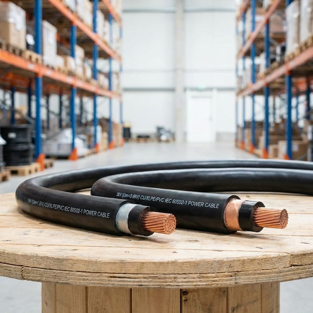
Product Definition: Low-voltage extrusion-insulated power cable for 1kV and 3kV systems, made with high-conductivity copper or aluminum conductors and premium extrusion insulation.
See Details
Insulated Power Cables | Technical Specifications, Structure and Industrial Applications
Jul 02,2026
Content
Industry technical brief
Insulated Power Cables are electrical conductors surrounded by a dielectric material layer designed to contain electrical current within a defined path while preventing unintended contact between the conductor and surrounding equipment, personnel, or other conductive surfaces. This category of cable forms one of the foundational components in industrial power distribution, serving as the physical medium through which electrical energy is transmitted from source to load across manufacturing plants, utility networks, and engineered systems. The insulation layer is not a passive covering but an active electrical barrier engineered to specific dielectric, thermal, and mechanical performance requirements based on the voltage class and operating environment of the installation. Understanding how this component is constructed, how it performs under load, and how it is specified for different applications provides a practical foundation for procurement teams and engineering personnel responsible for selecting cable products for industrial infrastructure projects.
01 Definition
Definition and technical classification
An insulated power cable consists of one or more conductors, typically copper or aluminum, surrounded by an insulating material that separates the current carrying path from the outer environment. The conductor is responsible for carrying load current, while the insulation layer is responsible for containing the associated electric field and preventing leakage current or dielectric breakdown under normal and fault conditions. In multi core designs, each conductor is individually insulated before being assembled together under a common outer jacket, which provides mechanical protection and, in many designs, an additional barrier against moisture and chemical exposure.
Cables in this category are generally classified by voltage rating, insulation material type, conductor configuration, and installation environment. Low voltage cables typically operate below 1000 volts and are used extensively in general industrial wiring, control panels, and equipment interconnections. Medium voltage cables extend into the tens of kilovolts range and are commonly applied in distribution feeders, substation interconnections, and large industrial power systems. High voltage cables are engineered for transmission level applications, where insulation thickness and shielding design become significantly more demanding due to the higher electric field stress present at these voltage levels.
Common insulation materials include cross linked polyethylene, ethylene propylene rubber, and polyvinyl chloride, each selected based on required dielectric strength, thermal rating, and resistance to environmental degradation. Material selection directly determines the cable's continuous operating temperature, short circuit withstand capability, and expected service life under specified load conditions.
02 Mechanism
Working principle and technical mechanism
The core function of insulation in a power cable is to maintain a controlled electric field around the conductor while preventing current from flowing outside the intended path. When voltage is applied to the conductor, an electric field forms across the insulation layer, with field intensity varying based on conductor geometry, insulation thickness, and applied voltage. The insulation material must withstand this continuous electrical stress without experiencing dielectric breakdown, partial discharge, or gradual material degradation over the operating life of the cable.
In medium and high voltage cable designs, semiconducting shield layers are applied on both the conductor surface and the outer insulation surface. These layers smooth the electric field distribution, eliminating localized stress concentrations that would otherwise accelerate insulation aging. Without proper shielding, sharp discontinuities at the conductor surface can generate partial discharge activity, which progressively degrades the insulation structure over time and shortens cable service life.
Thermal behavior is another critical mechanism in cable performance. As current flows through the conductor, resistive losses generate heat that must dissipate through the insulation and outer jacket into the surrounding environment. Insulation materials are rated for maximum continuous conductor temperature, and exceeding this threshold accelerates thermal aging, reducing the mechanical and dielectric properties of the material over the cable's operating lifetime. Cable ampacity calculations account for this thermal relationship, balancing conductor size, insulation thermal rating, and installation conditions such as burial depth, ambient temperature, and grouping with other cables in the same duct bank or tray.
Grounding and shielding configuration also play a role in the overall electrical mechanism of an insulated cable system. In shielded designs, a metallic layer surrounds the insulation and is bonded to ground at defined points along the cable route. This shield confines the electric field within the cable structure, reduces electromagnetic interference with nearby equipment, and provides a defined path for fault current in the event of an insulation failure, which supports faster fault detection and improved system protection coordination.
03 Specifications
Technical specifications and performance requirements
Selecting an insulated power cable for an industrial application requires evaluation across several interdependent performance parameters. Voltage rating determines the required insulation thickness and dielectric strength, while conductor cross sectional area determines current carrying capacity under specified thermal limits. Insulation resistance and dielectric withstand voltage are tested to confirm the cable can operate safely under both normal and transient overvoltage conditions, including switching surges and lightning related transients on outdoor systems.
Mechanical performance factors include tensile strength, bending radius tolerance, and resistance to abrasion during installation and operation. Bending radius limits are particularly relevant during installation, since exceeding the specified minimum radius can create localized stress on the insulation structure, potentially leading to premature failure at that point along the cable run. For cables installed in harsh industrial environments, resistance to chemical exposure, ultraviolet degradation, and moisture ingress becomes equally important, particularly for outdoor, underground, or marine applications where the cable jacket is continuously exposed to environmental stress over an extended service period.
Fire performance characteristics are increasingly specified alongside standard electrical and mechanical parameters. Depending on the installation environment, cables may be required to meet flame retardant, low smoke, or halogen free requirements, particularly in enclosed industrial spaces, tunnels, or facilities where smoke density and toxic gas release during a fire event are safety critical concerns.
| Parameter | Typical requirement | System relevance |
| Voltage rating | Low, medium, or high voltage class | Defines insulation thickness and clearance requirements |
| Conductor material | Copper or aluminum, stranded or solid | Determines current capacity and resistance losses |
| Insulation type | XLPE, EPR, or PVC compound | Determines thermal rating and dielectric strength |
| Temperature rating | Continuous operating temperature limit | Affects ampacity and long term insulation aging |
| Shielding structure | Conductor and insulation semiconducting layers | Controls electric field distribution and reduces discharge |
| Mechanical rating | Bending radius and tensile strength limits | Determines installation method and routing constraints |
| Fire performance | Flame retardant or low smoke rating | Required for enclosed or safety critical installations |
04 Applications
Application scenarios in industrial systems
Insulated power cables are deployed across a broad range of industrial and infrastructure systems. In manufacturing facilities, they distribute power from main switchgear to production line equipment, motor control centers, and automated process machinery, where consistent voltage delivery and thermal stability are required for continuous operation. Facility layouts often require cables to be routed through cable trays, conduit systems, or overhead raceways, each of which imposes different mechanical and thermal considerations on cable selection.
In underground and buried installations, cables must be selected with jacket materials resistant to soil chemistry, moisture penetration, and mechanical loading from surrounding backfill. Direct buried cable systems also require attention to thermal resistivity of the surrounding soil, since poor heat dissipation in the ground can reduce the effective current carrying capacity of an otherwise correctly rated cable. Substation and switchgear interconnections rely on cables with precise dielectric performance to maintain safe clearance and insulation coordination between system components operating at different voltage levels.
Renewable energy systems, including solar and wind installations, use insulated power cables to connect generation equipment to inverters, transformers, and grid interconnection points, often requiring resistance to ultraviolet exposure and extended outdoor service conditions. System integrators and engineering contractors also specify insulated power cables for panel wiring, distribution feeders, and interconnections between control systems and field equipment, where cable performance directly affects system reliability and maintenance requirements.
05 Integration
Procurement and system integration considerations
For technical procurement managers and system integrators, cable selection extends beyond individual product specifications to include compatibility with the broader electrical system. Cable sizing must align with upstream protection devices, including circuit breakers and fuses, to ensure that fault current withstand ratings and thermal limits are coordinated across the entire distribution path. Mismatched cable and protection device ratings can result in either premature protective device operation or inadequate protection of the cable during fault conditions.
Termination and jointing methods also factor into system level reliability. Cable terminations must be compatible with the insulation and shielding structure of the selected cable, since improperly matched termination kits can introduce localized electrical stress points that compromise the integrity of an otherwise correctly specified cable. For medium and high voltage systems, this typically requires stress control components designed specifically for the insulation type and voltage class in use.
Documentation and traceability requirements are increasingly part of B2B procurement processes, with buyers requesting material certificates, test reports, and compliance documentation covering dielectric testing, mechanical testing, and fire performance testing where applicable. This supports both regulatory compliance and long term asset management, since accurate records of installed cable specifications assist maintenance teams during future system expansions or fault investigations.
06 Trends
Industry development trends and future outlook
Industrial power distribution systems are trending toward higher operating temperatures and increased current density, driving demand for insulation materials with improved thermal endurance and longer projected service life. Material science developments continue to refine cross linked polyethylene formulations and alternative dielectric compounds to achieve higher dielectric strength while maintaining flexibility and mechanical durability required for practical installation.
Increased integration of distributed energy resources, including solar generation and battery storage systems, is expanding demand for cables rated for variable load profiles and outdoor exposure conditions. At the same time, growing emphasis on system monitoring is influencing cable design, with some installations incorporating embedded sensing capability to track insulation condition, temperature, and load over the operational lifetime of the installation, supporting predictive maintenance strategies rather than reactive replacement cycles.
Regulatory and safety standards continue to evolve, placing greater emphasis on fire performance, low smoke characteristics, and environmental compliance across insulation and jacket materials. These trends are shaping procurement specifications across industrial, utility, and infrastructure projects, requiring closer alignment between cable design parameters and system level performance targets.
Summary
Conclusion
Insulated power cables function as a foundational element within industrial electrical systems, providing controlled current transmission through engineered dielectric materials designed to withstand defined voltage, thermal, and mechanical conditions. Their performance directly affects the safety, reliability, and operational continuity of the systems they support, from manufacturing facilities and substations to renewable energy installations and distribution networks. Proper specification requires coordination across electrical, mechanical, and environmental performance parameters, along with careful attention to system level compatibility with protection devices and termination methods. As industrial systems continue to evolve toward higher power density and more demanding operating environments, the technical specification and material selection of insulated power cables remain a central consideration for engineering teams, procurement managers, and system integrators responsible for long term infrastructure performance.
Related products
-
-
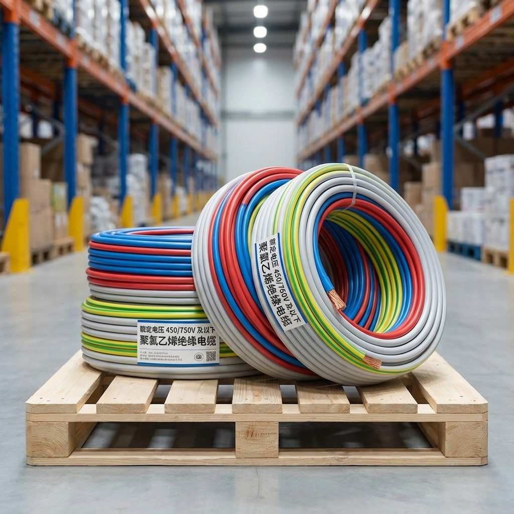
Product Overview: This series consists of general-purpose wires and cables with a rated voltage of 450/750V and below, using polyvinyl chloride (PVC) insulation and sheathing. Featuring mature technol...
See Details -
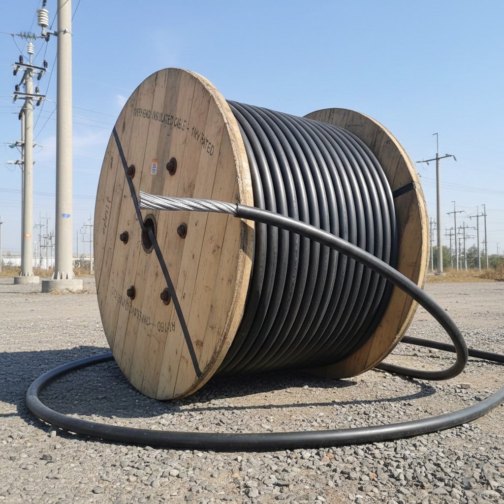
Product Overview: Designed specifically for overhead power line installation, this product is suitable for distribution lines with a rated voltage of 1kV and below, making it an ideal choice for urban...
See Details -
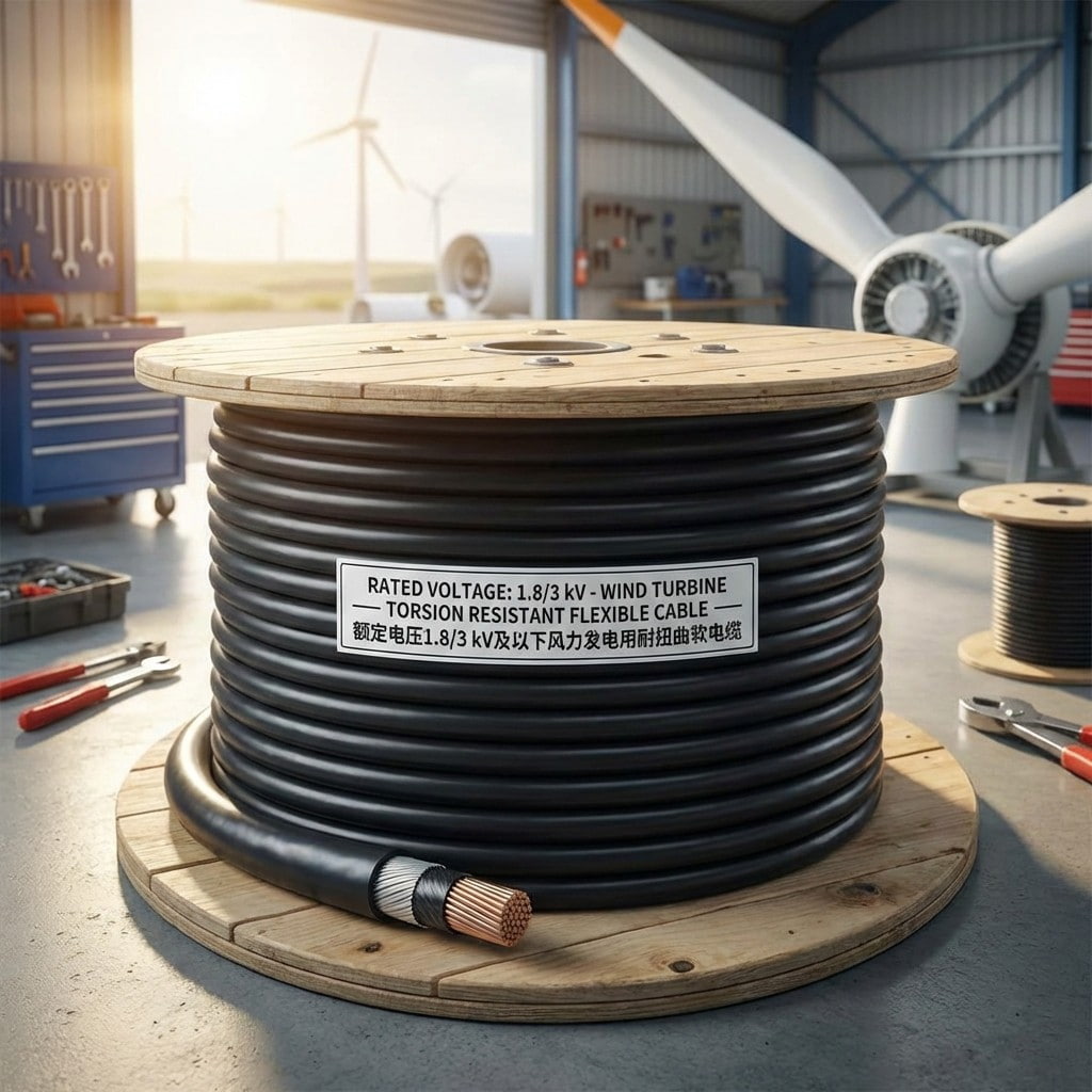
Product Introduction: Designed specifically for the harsh operating environment of wind power systems, meeting the requirements of continuous torsion and bending during mobile installation within the...
See Details -
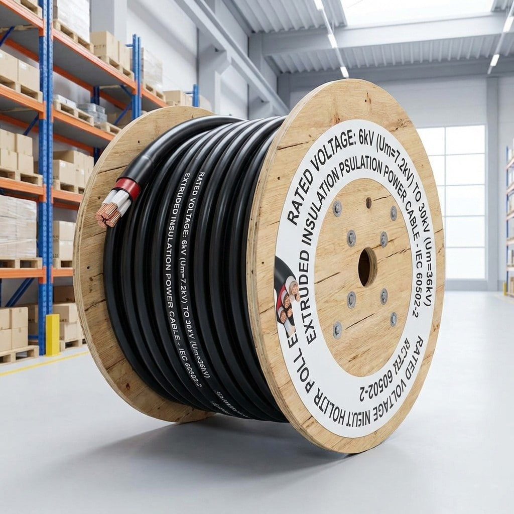
Product Definition: Medium-voltage extrusion-insulated power cable for 6kV to 30kV systems, using high-quality copper or aluminum conductors and premium insulation materials, designed for medium-volta...
See Details -
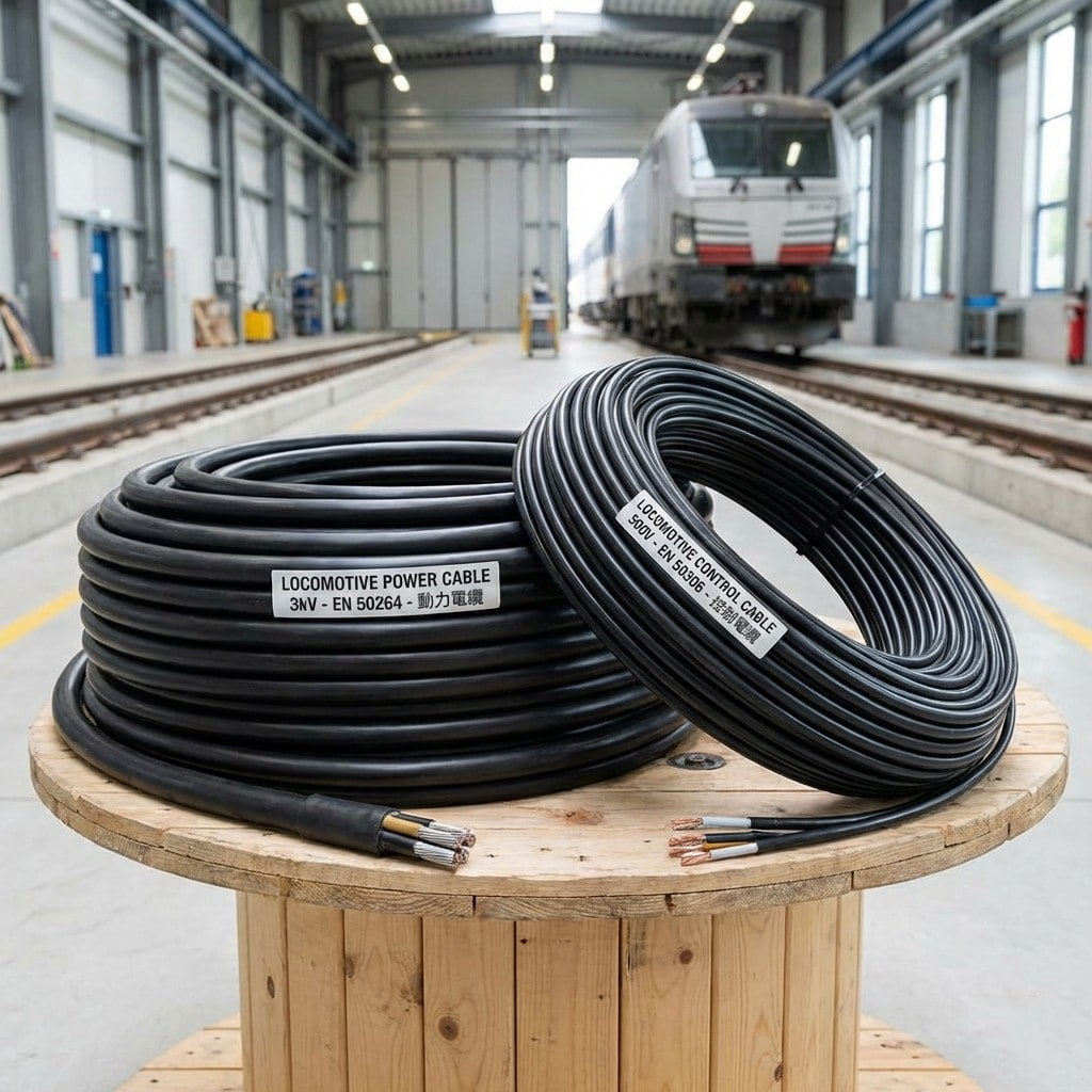
Product Introduction: Locomotive and rolling stock cables are specifically designed for the rail transit industry, covering both power supply and control signaling. The cables utilize highly flexible ...
See Details
- About Us
- Company Profile
- History
- Smart Factory
- Resources
- Resources
- Technical Datasheets
- Product Catalogs
- Certificates & Compliance
- Industry Standards
- FAQs
- News
- Products
- Power Cables
- Electrical Equipment Cables
- Wind Power Cables
- Photovoltaic / Energy Storage Cables
- Overhead Cables
- Rail Transit
- Contact
- Contact
- Contact Meaia
-
Mobile QR code

Back to top

