
 English
  中文简体
中文简体 

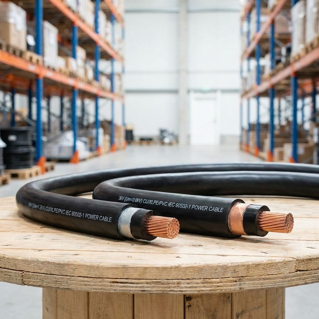
Product Definition: Low-voltage extrusion-insulated power cable for 1kV and 3kV systems, made with high-conductivity copper or aluminum conductors and premium extrusion insulation.
See Details
Energy Storage Cable Guide: Functions, Types & Sizing
Jul 16,2026
Content
- 1 Introduction: The Critical Role of Energy Storage Cables in Modern Power Systems
- 2 Defining the Energy Storage Cable: Core Components and Characteristics
- 3 Technical Specifications and Key Performance Factors
- 4 Application Scenarios Across the Energy Storage Landscape
- 5 Comparative Analysis: Energy Storage Cables vs. Standard Power Cables
- 6 Selecting the Correct Energy Storage Cable: A Practical Guide
- 7 Installation, Operation, and Maintenance Considerations
- 8 Common Mistakes in Energy Storage Cable Selection
- 9 Conclusion
- 10 Frequently Asked Questions
- 10.1 What is an energy storage cable and why is it different from a standard power cable?
- 10.2 How do I choose the right cable size for my energy storage system?
- 10.3 What are the key performance factors for an energy storage cable?
- 10.4 Why is insulation material important for energy storage cables?
- 10.5 What does "LSZH" mean in the context of energy storage cables?
- 10.6 How often should energy storage cables be inspected?
- 10.7 Can energy storage cables be used for both AC and DC applications?
- 10.8 What standards govern the manufacturing of energy storage cables?
Introduction: The Critical Role of Energy Storage Cables in Modern Power Systems
The rapid global expansion of renewable energy generation has catalyzed a parallel surge in the deployment of energy storage systems (ESS). These systems, ranging from residential battery units to utility-scale storage plants, are fundamental to grid stability and the effective utilization of intermittent power sources like solar and wind. At the heart of every functional ESS lies a component that, while often overlooked, is essential to its performance, safety, and longevity: the energy storage cable.
An energy storage cable is not a generic power cord. It is a specialized interconnect designed to handle the unique electrical, thermal, and mechanical demands of battery-based systems. These cables form the neural and vascular network of a storage installation, linking battery modules, battery clusters, power conversion systems (PCS), inverters, and the grid interface. Their primary function is to transmit high direct current (DC) and alternating current (AC) power efficiently, safely, and reliably through the system's charge and discharge cycles, which can number in the thousands over the asset's lifetime.
The global market for these specialized cables reflects their increasing importance. Valued at US$ 5.57 billion in 2024, the market is projected to reach US$ 7.72 billion by 2031, driven by the accelerating adoption of energy storage worldwide. This growth underscores a critical need for industry professionals—from project contractors to procurement specialists—to understand the technical nuances of cable selection to ensure system optimization and long-term asset protection. This guide provides a comprehensive overview of the technical specifications, key performance factors, and selection criteria for energy storage cables, offering a valuable resource for technical decision-makers.
Defining the Energy Storage Cable: Core Components and Characteristics
An energy storage cable is engineered for high-performance electrical connections within battery energy storage systems (BESS), ensuring safe and efficient power transmission between battery packs, inverters, and grid interfaces. Unlike standard building wire, these cables are designed to endure the rigors of energy storage applications, including high current loads, frequent thermal cycling, exposure to chemicals, and confined installation spaces. A typical storage cable consists of three main layers, each contributing to its overall performance.
1. Conductor
The conductor is the core pathway for electricity. High-conductivity materials are critical to minimize resistive (I²R) power losses during transmission. Stranded bare copper is the industry standard due to its excellent conductivity, flexibility, and durability. Aluminum conductors may be used in larger gauges for fixed installations where weight is a concern, but they require larger cross-sectional areas to achieve comparable ampacity and demand specific termination techniques to prevent galvanic corrosion. The stranding of the conductor is also a key characteristic; fine stranding significantly enhances flexibility, which is essential for installations with tight bending radii and for cables that may be subjected to vibration.
2. Insulation and Jacket
The insulation is a critical safety and performance barrier. It must provide robust electrical isolation, prevent short circuits, and protect the conductor from mechanical damage and environmental factors. For energy storage applications, cross-linked polyethylene (XLPE) and ethylene propylene rubber (EPR) are among the most common and effective materials. XLPE offers a high dielectric strength, excellent thermal properties, and good resistance to moisture and chemicals. The outer jacket, often made from thermosetting compounds like chlorinated polyethylene (CPE) or polyurethane, provides an additional layer of protection against abrasion, oil, UV radiation, and extreme temperatures. The combination of high-quality insulation and a durable jacket directly impacts the cable's lifespan, which is typically rated for 20-30 years in service.
3. Shielding
In many applications, especially those with high-power, fast-switching power electronics (like inverters and converters), an effective shielding layer is crucial. Shielding minimizes electromagnetic interference (EMI) that can disrupt communication, control, and protection systems within the ESS. A metallic shield, typically in the form of a copper tape or a braided wire layer, serves to contain the electromagnetic field within the cable. This protects sensitive electronics and ensures the system complies with stringent electromagnetic compatibility (EMC) standards.
Technical Specifications and Key Performance Factors
Specifying the correct energy storage cable requires a thorough examination of several key technical parameters. These specifications are not merely numbers on a datasheet; they define the cable's ability to perform safely and effectively over its operational life. The following table summarizes some of the most critical specifications for an energy storage cable.
| Parameter | Description & Typical Values |
|---|---|
| Rated Voltage (U₀/U) | 1.8/3 kV, 1.5/1.5 kV, or 600/1000 V AC/DC. The maximum continuous operating voltage the cable can withstand. |
| Temperature Rating (Conductor) | Typically 90°C for continuous operation, with short-circuit tolerance up to 250°C for XLPE insulation. |
| Minimum Bending Radius | Often specified as a multiple of the overall cable diameter (e.g., 5D for fixed installation, 8D for flexible). |
| Conductor Material | Stranded bare copper (Class 5/6 stranding) for flexibility and high conductivity. |
| Insulation Material | Cross-linked Polyethylene (XLPE) or Ethylene Propylene Rubber (EPR). |
| Outer Sheath Material | Thermosetting compound (e.g., CPE) providing oil, UV, and abrasion resistance. |
| Flammability Rating | VW-1, FT-1, or IEC 60332-1-2 for flame retardancy, often required by safety codes. |
| Halogen Content | Low Smoke Zero Halogen (LSZH) or Halogen-Free Flame Retardant (HFFR) options are often mandatory for indoor or confined spaces. |
Performance Factors
Beyond the specifications, the performance of an energy storage cable is judged by several key factors. Ampacity, or the maximum current a cable can carry safely, is determined by conductor size, material, insulation temperature rating, and ambient conditions. Voltage drop is a critical consideration for system efficiency; excessive voltage drop reduces energy delivered to the load and generates heat. This is directly related to the cable's resistance, which is a function of its length and cross-sectional area. Insulation resistance is another key metric, measured in megaohms per kilometer, ensuring the integrity of the insulation to prevent leakage currents and potential faults.
Application Scenarios Across the Energy Storage Landscape
Energy storage cables are deployed across a wide spectrum of applications, from small-scale residential backup systems to massive grid-stabilization projects. Each scenario presents unique environmental and technical demands, requiring careful cable specification to ensure reliable and safe operation.
- 1. Utility-Scale Battery Energy Storage Systems (BESS)
In large-scale installations, cables are responsible for connecting thousands of individual battery cells into modules, racks, and ultimately, to the grid-tied PCS. These cables are often longer and experience higher currents than those in smaller systems. They are frequently installed in outdoor environments, on racks, or in trenches, demanding robust mechanical and environmental protection, including UV resistance, water resistance, and high mechanical strength. The fire safety rating of cables in these applications is paramount, often requiring cables with LSZH or flame-retardant properties to minimize risk in densely packed containers or fenced compounds.
- 2. Commercial and Industrial (C&I) Storage
C&I systems are typically installed in commercial buildings, factories, and warehouses. These environments present unique challenges, including exposure to chemicals, oils, and mechanical abuse from forklifts and other equipment. Cables installed in these areas often require durable jackets that are oil-resistant and abrasion-resistant. Installation may involve cable trays, conduits, or direct burial, each dictating specific mechanical protection requirements. The cable's flexibility can also be a key factor for installations in tight machine rooms or where space is at a premium.
- 3. Residential and Small-Scale Storage
Residential systems, while smaller, are typically installed in homes, garages, or outdoors. Here, safety is the primary concern, as cables are in close proximity to living spaces. Cables must be flame retardant and often require a LSZH classification to limit smoke and toxic fumes in the event of a fire. Ease of installation, flexibility, and a compact design are also important for these applications.
- 4. Electric Vehicle (EV) Charging and Marine Applications
The growing EV charging infrastructure, particularly DC fast-charging stations, represents a significant application for these cables. These cables handle very high currents and are frequently handled by the end-user, necessitating exceptional flexibility and mechanical durability. The cables must also withstand the elements and constant flexing. Similarly, marine and offshore energy storage applications demand extreme resistance to saltwater, moisture, and vibration, with sheathing and insulation designed for these rigorous conditions.
Comparative Analysis: Energy Storage Cables vs. Standard Power Cables
While a standard building wire might appear similar at first glance, it is not suitable for use within an energy storage system. The differences are rooted in the engineering requirements of the application. The table below highlights the critical distinctions between a purpose-built energy storage cable and a general-purpose power cable, such as THHN or building wire.
| Feature | Energy Storage Cable | Standard Power Cable |
|---|---|---|
| Flexibility | High (Class 5/6 stranding), designed for frequent flexing and tight bends. | Low (Class 2 stranding), stiff, intended for fixed installations. |
| Insulation/Jacket | Robust XLPE, EPR, CPE, or TPU; often LSZH or Flame Retardant. | Typically PVC or nylon, may be flame retardant but not always LSZH. |
| Temperature Rating | High (90°C - 105°C continuous), high short-circuit tolerance. | Typically 60°C - 75°C for older types, up to 90°C for modern types. |
| Environmental Resistance | Designed for UV, oil, chemical, and moisture resistance. | Limited resistance, often not suitable for outdoor or harsh environments. |
| Safety Standards | Meets stringent UL 1164, UL 10281, UL 1072, or CSA C22.2 standards. | Meets UL 83, UL 44, or similar general building wire standards. |
| Application Focus | Battery interconnects, high-power DC, and AC circuits in ESS. | Building wiring, general power distribution, and lighting circuits. |
Selecting the Correct Energy Storage Cable: A Practical Guide
Selecting the correct cable size and type for an energy storage system is a critical engineering decision that directly impacts system performance, safety, and capital cost. An oversized cable adds unnecessary cost, while an undersized cable creates a fire hazard, reduces system efficiency, and shortens cable life. The following factors are central to a sound selection process.
1
Conductor Sizing and Ampacity
The process begins with calculating the maximum continuous and short-circuit currents the cable will carry. Ampacity ratings, as defined by standards like the National Electrical Code (NEC) or the International Electrotechnical Commission (IEC), are based on conductor size, insulation temperature rating, and ambient temperature. It is crucial to apply correction factors for installation conditions, such as derating for multiple cables in a bundle or for elevated ambient temperatures. A common oversight is failing to account for the high DC currents in battery systems, which can exceed the AC rating for the same conductor size due to the lack of a "skin effect" in DC, potentially allowing for a slightly smaller conductor for the same ampacity. However, the system voltage drop and fault current withstand capabilities are often more critical constraints.
2
Voltage Drop Considerations
Voltage drop (VD) should be limited to a maximum of 2-3% of the nominal system voltage to ensure efficient energy transfer. Excessive VD leads to increased losses, which generate unnecessary heat, reduce the efficiency of the battery system, and can impair the performance of connected equipment. The VD is directly proportional to the cable length and current, and inversely proportional to the conductor cross-sectional area. For long cable runs, which are common in utility-scale systems, this factor often dictates using a larger conductor size than what is required by ampacity alone. The formula for voltage drop is a fundamental tool for the design engineer.
3
Mechanical and Environmental Factors
The physical installation environment is a primary driver for cable jacket and insulation selection. For outdoor or direct-burial applications, an UV-stabilized, moisture-resistant jacket is mandatory. In an environment with oils, coolants, or lubricants, an oil-resistant jacket such as CPE or TPU is necessary. For applications with significant movement or vibration, such as on battery rack shuttles, a highly flexible, fine-stranded cable is required to prevent conductor fatigue and failure. The cable's minimum bending radius, a measure of its flexibility, must be considered to ensure it can be routed without damaging the insulation or conductor.
4
Regulatory Compliance and Safety Standards
Compliance with UL, CSA, and IEC standards is not just a formality; it is often a legal requirement and is essential for securing project insurance and approvals. Key standards include UL 1164 (for battery cables), UL 1072, and CSA C22.2 No. 38. These standards specify requirements for flammability, physical performance, electrical properties, and environmental testing. A cable's rating, such as VW-1 for flame resistance, is a direct outcome of meeting these standards. Always consult the relevant local codes (e.g., the NEC in the US) to ensure the selected cable meets the requirements for the specific installation.
Installation, Operation, and Maintenance Considerations
Even the best cable can fail if not installed and maintained correctly. Following best practices is essential for maximizing the lifespan and reliability of the cable infrastructure in an ESS.
Installation Best Practices
Proper installation begins with careful handling to avoid nicks and cuts in the insulation. Cables should be routed in a way that respects the manufacturer-specified minimum bending radius. Forcing a cable into a tight bend can stress the conductor and insulation, creating a long-term failure point. Cables in cable trays should be secured with appropriate ties, but over-tightening can damage the jacket. Provide adequate separation between power cables and control/communication cables to prevent electromagnetic interference. When installing cables in parallel to increase ampacity, ensure that the cables are of equal length and have identical terminations to ensure even current sharing.
Operation and Maintenance
An effective maintenance program includes regular thermal imaging of terminations to detect hot spots. An elevated temperature at a termination can indicate a loose connection or a failing terminal. Visual inspections for damage to the jacket or insulation should be conducted periodically. In harsh environments, the frequency of these inspections should be increased. Maintaining clear and accurate documentation of cable routing, size, and type is invaluable for troubleshooting and future system expansions.
Common Mistakes in Energy Storage Cable Selection
In the process of designing a BESS, several common mistakes regarding cable selection can be avoided with a thorough understanding of the system's requirements.
- 1. Under-sizing the Cable
Perhaps the most critical error is choosing a cable with insufficient ampacity. This often occurs when only the nominal current is considered, without accounting for derating factors, inrush currents, or potential future system expansion. An undersized cable will overheat, leading to accelerated insulation degradation, increased electrical resistance, and a significant fire risk.
- 2. Using the Wrong Insulation Type
Selecting a standard PVC-insulated cable for an energy storage system is a common mistake. PVC is less flexible, has a lower maximum operating temperature, and is generally less flame-retardant compared to XLPE or EPR. In a high-energy environment, this can lead to premature cable failure and safety hazards.
- 3. Ignoring the Mechanical Requirements
Overlooking the installation environment's mechanical demands is another frequent pitfall. A cable with a standard jacket can be quickly damaged by abrasion, chemicals, or UV radiation. This can compromise the cable's integrity and create a point of failure. Always specify a cable with a jacket that matches the specific environmental hazards it will face.
Conclusion
The selection and specification of an energy storage cable is a fundamental engineering task that influences the efficiency, safety, and financial viability of a battery energy storage system. It is not a component to be treated as a commodity, but as a critical element of the system's infrastructure. A thorough understanding of the cable's construction—from the stranded copper conductor to the specialized XLPE insulation and durable, halogen-free jacket—is essential for making informed decisions.
By carefully evaluating the specific application requirements, from the high-ampacity needs of utility-scale BESS to the flexibility demands of dynamic installations, professionals can ensure they select a cable that meets the rigorous performance standards of modern energy storage. Adhering to technical specifications, understanding the differences from standard power cables, and avoiding common selection mistakes will lead to a more reliable, safer, and more cost-effective energy storage solution. As the energy transition accelerates, the role of these specialized interconnects will only grow in importance, solidifying their place as a cornerstone of energy storage technology.
Frequently Asked Questions
What is an energy storage cable and why is it different from a standard power cable?
An energy storage cable is a specialized electrical cable designed for high-performance connections within battery systems. It differs from standard building wire in its exceptional flexibility, high-temperature insulation (XLPE or EPR), robust mechanical protection (oil and UV-resistant jackets), and compliance with specific safety standards like UL 1164. These features ensure it can handle the high currents and harsh environments typical of energy storage applications.
How do I choose the right cable size for my energy storage system?
Selecting the right cable size is a multi-step process. First, calculate the maximum continuous and short-circuit currents the cable will carry. Then, refer to ampacity tables for the cable's insulation temperature rating, applying correction factors for ambient temperature and bundling. Also, verify that the voltage drop over the cable's length remains within acceptable limits (typically 2-3%). The final choice must satisfy both the ampacity and voltage drop requirements.
What are the key performance factors for an energy storage cable?
The most critical performance factors include ampacity (current-carrying capacity), resistance (which affects voltage drop and power loss), insulation resistance (to prevent leakage currents), and thermal stability (the ability to withstand high and fluctuating temperatures). The cable's flexibility and its resistance to environmental factors like oil, UV, and abrasion are also crucial for long-term reliability.
Why is insulation material important for energy storage cables?
The insulation material is vital because it provides electrical isolation, prevents short circuits, and protects the conductor from heat and the environment. Materials like XLPE are chosen for their excellent dielectric strength and ability to withstand the high continuous operating temperatures (90°C) and short-circuit temperatures (250°C) that are common in battery systems.
What does "LSZH" mean in the context of energy storage cables?
LSZH stands for Low Smoke Zero Halogen. It refers to a cable's jacket and insulation materials that emit limited smoke and no toxic halogen gases when exposed to fire. This is a critical safety feature for indoor installations where personnel and sensitive equipment need to be protected from the effects of a fire.
How often should energy storage cables be inspected?
The inspection frequency depends on the application and the environment. A general recommendation is to perform a visual inspection and thermal imaging check of terminations at least annually. In harsh or high-use environments, quarterly or even monthly inspections are advisable to catch any signs of degradation early.
Can energy storage cables be used for both AC and DC applications?
Yes, many energy storage cables are rated for both AC and DC applications up to their specified voltage rating (e.g., 1.8/3 kV). They must be selected based on the specific system's current and voltage requirements, ensuring the rating is appropriate for the application.
What standards govern the manufacturing of energy storage cables?
Key standards include UL 1164 (for battery cables), UL 1072 (for medium-voltage cables), CSA C22.2 No. 38, and various IEC standards. These standards set requirements for electrical performance, physical properties, and fire safety to ensure the cables are safe and reliable for their intended use.
Related products
-
-
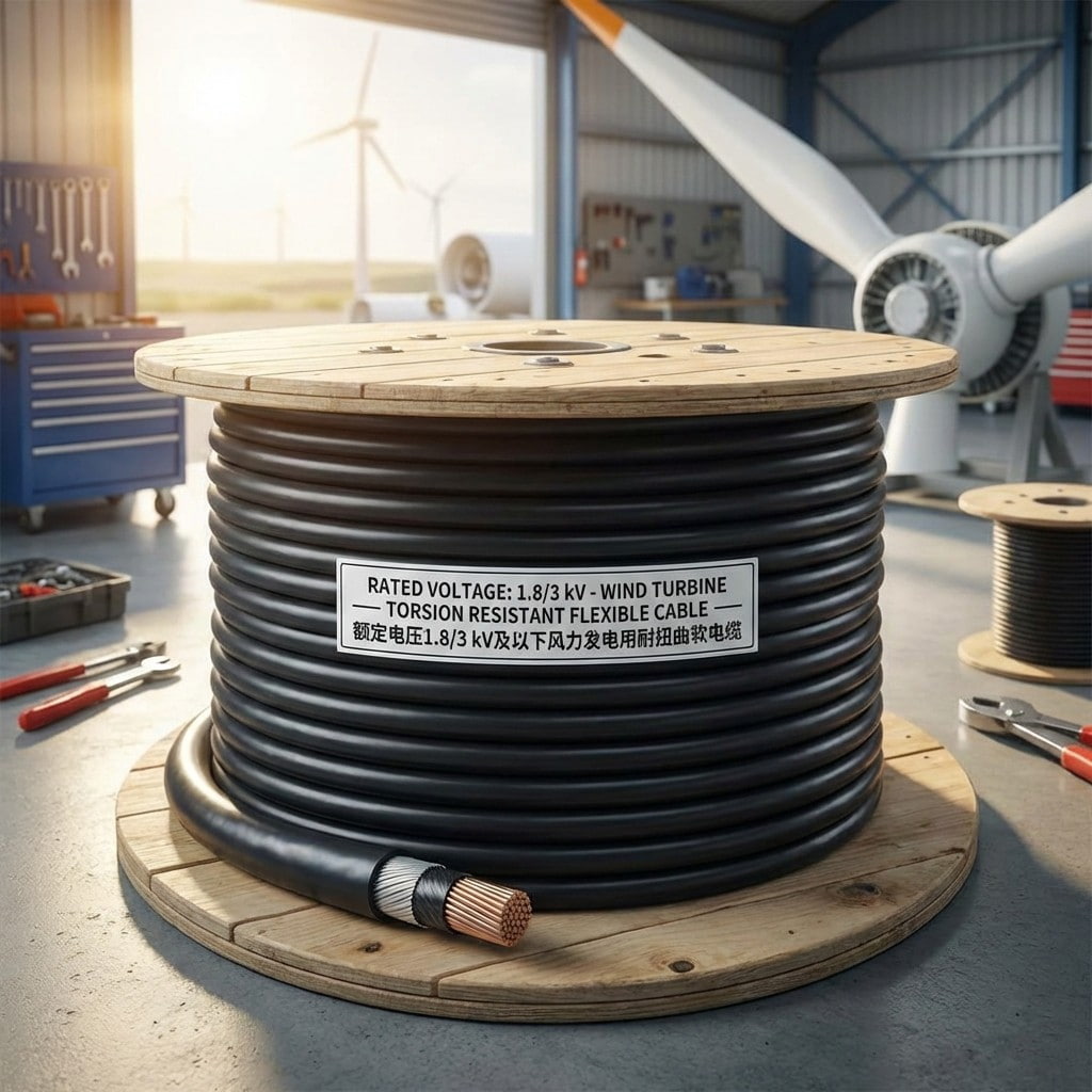
Product Introduction: Designed specifically for the harsh operating environment of wind power systems, meeting the requirements of continuous torsion and bending during mobile installation within the...
See Details -
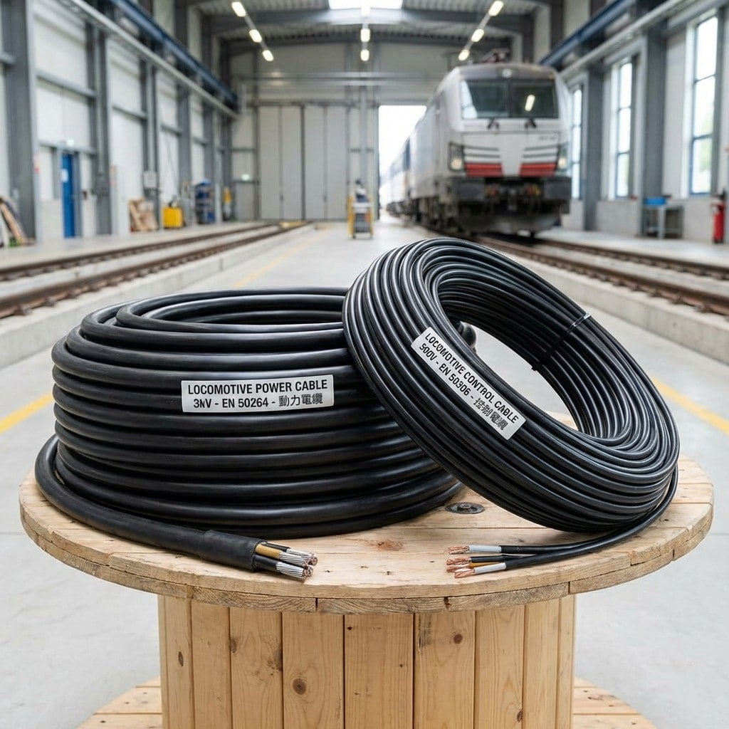
Product Introduction: Locomotive and rolling stock cables are specifically designed for the rail transit industry, covering both power supply and control signaling. The cables utilize highly flexible ...
See Details -
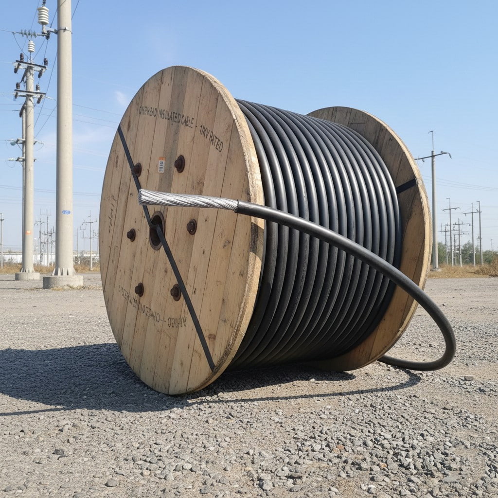
Product Overview: This product is an overhead insulated cable specifically designed for 10kV distribution networks, using cross-linked polyethylene (XLPE) as the insulation layer. It upgrades traditio...
See Details -
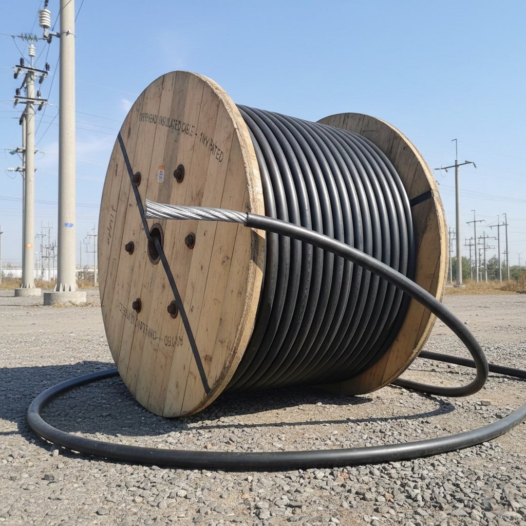
Product Overview: Designed specifically for overhead power line installation, this product is suitable for distribution lines with a rated voltage of 1kV and below, making it an ideal choice for urban...
See Details -
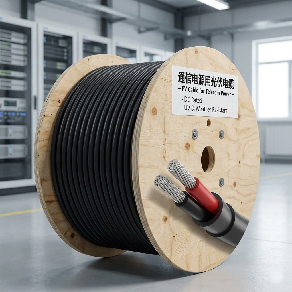
Product Overview: Designed specifically for photovoltaic power supply systems in communication base stations, data centers, etc., this product transmits DC power from photovoltaic modules to communica...
See Details
- About Us
- Company Profile
- History
- Smart Factory
- Resources
- Resources
- Technical Datasheets
- Product Catalogs
- Certificates & Compliance
- Industry Standards
- FAQs
- News
- Products
- Power Cables
- Electrical Equipment Cables
- Wind Power Cables
- Photovoltaic / Energy Storage Cables
- Overhead Cables
- Rail Transit
- Contact
- Contact
- Contact Meaia
-
Mobile QR code

Back to top

