
 English
  中文简体
中文简体 

Product Overview: This product utilizes a double-layer co-extrusion insulation and electron irradiation cross-linking process, possessing halogen-free, low-smoke, and flame-retardant properties. It i...
See Details
What Does Shielding Actually Do in a Control Cable: Braided vs. Foil Compared
Jun 17,2026
Content
- 1 Why Shielding Is Not Optional in Modern Control Wiring
- 2 Foil Shielding: How a Thin Metallized Layer Blocks Noise
- 3 Braided Shielding: How a Woven Metal Mesh Provides Mechanical and Electrical Protection
- 4 Foil vs. Braided Shielding: Side-by-Side Comparison
- 5 Combination Shields: When Foil and Braid Work Together
- 6 Grounding and Termination: The Step That Determines Whether Shielding Works at All
- 7 Choosing Shield Type by Installation Environment
- 8 Inspection and Maintenance Practices for Shielded Control Cables
- 9 Frequently Asked Questions
- 9.0.1 Q1: What is the main functional difference between braided and foil shielding in a control cable?
- 9.0.2 Q2: Does foil shielding stop low-frequency magnetic interference as well as braided shielding?
- 9.0.3 Q3: Can a control cable use both foil and braided shielding at the same time?
- 9.0.4 Q4: Why does grounding the shield at both ends sometimes make noise worse instead of better?
- 9.0.5 Q5: How often should shielded control cables be inspected for damage?
- 9.0.6 Q6: Is a higher braid coverage percentage always better for noise protection?
Why Shielding Is Not Optional in Modern Control Wiring
Control WiringEMI ShieldingIndustrial Automation
Control cables rarely carry power. Most of them carry 4 to 20 mA process signals, 0 to 10 V analog references, encoder pulses, or digital communication frames between a controller and a field device. Because these signals operate at low voltage and low current, they are far more sensitive to outside electrical noise than a power feeder ever would be. A control cable routed next to a variable frequency drive output, a contactor coil, or a bank of switching power supplies is constantly exposed to electromagnetic fields that can induce unwanted voltage directly onto the signal conductors.
Without a shield, that induced noise rides on top of the intended signal. In an analog loop, this shows up as drift or jitter in a reading that otherwise looked perfectly stable during a bench test. In a digital communication cable, it shows up as retransmissions, dropped packets, or intermittent faults that come and go depending on which nearby equipment happens to be running at that moment. These problems are notoriously difficult to troubleshoot because the wiring itself tests fine with a simple continuity meter; the fault only appears once the plant is operating under real load, and tracking it back to a specific cable run can cost hours of production downtime.
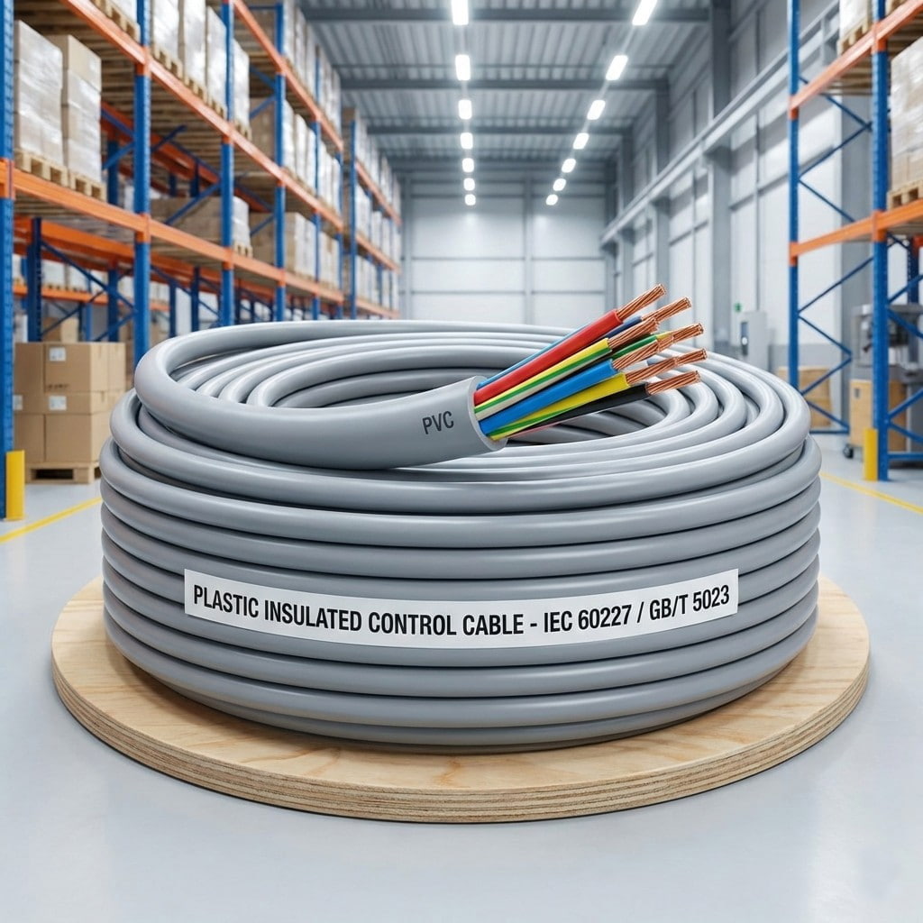
Selecting a properly shielded plastic insulated control cable for these runs is one of the more cost-effective interference fixes available, because the shielding decision is made once at the cable level rather than repeated as field patches every time a new noise source is added to the panel.
2main shield families used in control cable: foil and braided
95%coverage achievable with a tightly woven braided shield
1grounding point usually recommended for low frequency analog circuits
Capacitive Coupling From Nearby Power Wiring
When a control cable runs parallel to an unshielded power conductor for any meaningful distance, the two conductors form a small capacitor through the air and insulation between them. Voltage changes on the power conductor, especially the fast switching edges produced by variable frequency drives, couple a proportional voltage onto the control conductor. The longer the parallel run and the closer the spacing between the two cables, the stronger this coupling becomes.
Inductive Coupling From Switching Currents
Current loops, such as those formed by motor windings, contactor coils, and welding equipment, generate magnetic fields that expand and collapse as current switches on and off. A control cable sitting inside that changing magnetic field has a voltage induced directly into its conductors, independent of any direct electrical connection. This type of coupling is harder to stop with foil alone, because it depends on the magnetic properties of the shield rather than just its electrical continuity.
Foil Shielding: How a Thin Metallized Layer Blocks Noise
A foil shield is a thin laminate of aluminum bonded to a polyester carrier, wrapped longitudinally or spirally around the insulated conductors with an overlapping seam. Because the foil wraps continuously rather than as a woven mesh, it presents almost no gaps to the conductors underneath, which gives it close to full coverage against electric field coupling. A thin bare or tinned copper drain wire normally runs in contact with the foil along its length, since the foil itself is too thin and fragile to terminate directly with a connector or a soldered pigtail.
Foil performs best against high-frequency noise, generally above the tens of megahertz range, because at those frequencies a thin conductive surface is already an effective barrier and the lack of weave gaps prevents leakage. This makes foil shielding a strong, low-cost choice for instrumentation cables and twisted-pair data lines that mainly need protection from radiated radio-frequency noise rather than from heavy magnetic fields at the line frequency.
Where Foil Shielding Falls Short
The same thinness that keeps foil light and inexpensive also makes it the weaker option mechanically. Repeated flexing, a tight bend radius, or rough handling during installation can crack the aluminum layer, and once it cracks the shield becomes discontinuous at that point. A cracked foil shield does not always fail completely, but its effectiveness drops sharply at the damaged section, and the damage is invisible from outside the jacket. Foil also depends entirely on its drain wire for grounding, so a poorly terminated or broken drain wire effectively disables the entire shield even when the foil itself is still intact.
- Coverage: continuous wrap, close to full coverage of the insulated conductors
- Best suited frequency range: high frequency, mainly radiated noise
- Termination: relies on a single drain wire
- Flex tolerance: limited, prone to fatigue cracking over time
- Typical use: instrumentation pairs, fixed and low-flex installations
Braided Shielding: How a Woven Metal Mesh Provides Mechanical and Electrical Protection
A braided shield is constructed from many fine strands of bare or tinned copper, woven over the insulated conductors in two opposing directions, much like a fabric weave. The strands are grouped into carriers, and the number of carriers along with the weave angle determines how much of the underlying insulation the braid actually covers. Industrial control cables commonly use braids with somewhere between 16 and 36 carriers, achieving coverage in the range of roughly 60 to 95 percent depending on how tightly the carriers are packed together.
Because a braid is made of many interconnected strands rather than a single thin layer, it has a much lower overall resistance path to ground than a foil shield relying on one drain wire, and it tolerates flexing, vibration, and repeated cable tray movement far better. These properties make braided shielding the default choice for servo motor cables, cables on moving machine axes, and any installation where the cable will be flexed regularly over its service life.
The Tradeoff Behind the Weave
The same weave that gives a braid its strength also leaves small diamond-shaped gaps between the crossing strands. At high frequencies, where the wavelength becomes short relative to the gap size, radiated noise can leak through those gaps more easily than it would through a continuous foil layer. Increasing the carrier count or tightening the braid angle improves coverage and high-frequency performance, but it also adds weight, cost, and stiffness to the finished cable, so the choice usually comes down to balancing flexibility needs against the noise environment the cable will see in service.
- Coverage: typically 60 to 95 percent depending on carrier count and weave angle
- Best suited frequency range: low to mid frequency, strong against magnetically coupled noise
- Termination: can be soldered, crimped, or pigtailed directly without a separate drain wire
- Flex tolerance: high, suited to moving and vibrating installations
- Typical use: servo and motor feedback cables, cable tray runs, mobile equipment
Foil vs. Braided Shielding: Side-by-Side Comparison
The differences described above translate into a fairly predictable set of tradeoffs once they are placed side by side. Neither construction is universally better; each one solves a different part of the interference problem, which is why the comparison below is organized around the practical factors an engineer or installer actually has to weigh.
| Parameter | Foil Shield | Braided Shield |
|---|---|---|
| Best frequency range | High frequency, mainly radiated noise | Low to mid frequency, magnetically coupled noise |
| Typical coverage | Close to full, continuous wrap | About 60 to 95 percent depending on density |
| Flexibility and flex life | Lower, prone to fatigue cracking | Higher, suited to cable tray and moving uses |
| Mechanical robustness | Thin, easily damaged by crushing or pulling | Strong, resists abrasion and pulling forces |
| Termination method | Requires a separate drain wire | Soldered, crimped, or pigtailed directly |
| Relative weight and cost | Lighter, lower material cost | Heavier, higher material and labor cost |
| Typical applications | Instrumentation pairs, data lines | Servo cables, harsh mechanical environments |
In practice, the frequency content of the expected noise tends to drive the decision more than any other single factor. A cable exposed mainly to radiated radio-frequency noise from nearby switching electronics generally does well with foil alone, while a cable exposed to strong magnetic fields from motor or welding currents, or one that has to flex repeatedly, leans toward a braided construction even though it costs more.
60-95%typical braid coverage range across common carrier counts
Up to 100%coverage from a correctly overlapped foil wrap
16-36carriers commonly used in industrial control cable braids
Combination Shields: When Foil and Braid Work Together
Many control cables used in electrically noisy industrial settings combine a foil layer directly against the insulation with a braid wrapped over the top of it. The foil provides the continuous, gap-free barrier against high-frequency radiated noise, while the braid adds the low-resistance, mechanically tough path that handles lower-frequency magnetically coupled noise and gives the cable the flex life needed for real installations. The braid also protects the foil underneath from the abrasion and crushing that would otherwise crack it during pulling or while sitting in a cable tray.
This combination shield costs more and adds bulk to the finished cable, so it is generally reserved for applications where a single shield type has already proven insufficient, such as servo feedback cables running near drive output conductors, or instrumentation runs that must cross multiple distinct sources of electrical noise on their way to a control panel. Combination shielding has become increasingly common on PVC-insulated control cable assemblies built for variable frequency drive feedback loops, where both high-frequency switching noise and low-frequency magnetic coupling are present in the same run.
The extra cost is usually easy to justify once it is measured against the cost of an intermittent fault that takes a technician several visits to trace, especially on a cable that is difficult or expensive to replace once it is installed inside a machine or buried in a cable tray bundle with dozens of other conductors.
Grounding and Termination: The Step That Determines Whether Shielding Works at All
A shield, regardless of construction, only functions if the noise current it intercepts has a clear path to ground. The physical shield material is only half of the system; the termination method and grounding point are what actually determine whether that captured energy is drained away safely or left to find another path back into the circuit it was supposed to protect.
Single-Point vs. Multi-Point Grounding
Grounding a shield at a single point, normally at the control panel end, is the standard approach for most analog instrumentation cables, because it avoids creating a second current path between two ground references that may sit at slightly different potentials. Grounding at both ends can introduce a circulating current along the shield itself whenever those two ground points differ, even by a small amount, and that circulating current can induce noise onto the very conductors it was meant to protect. Multi-point grounding is sometimes used deliberately at higher frequencies, where keeping every grounding interval short compared to the noise wavelength matters more than avoiding a low-frequency ground loop, but this approach requires a level of grounding consistency that is uncommon in general industrial wiring.
A shield with a poor or inconsistent ground connection can perform worse than no shield at all, because it adds a new conductor capable of carrying noise current directly toward the sensitive circuit it was meant to protect.
Common Termination Mistakes
- Leaving the drain wire or pigtail longer than necessary, which turns it into an antenna instead of a clean ground path
- Grounding the shield at both ends on a low-frequency analog circuit without first confirming the ground potentials actually match
- Stripping back too much jacket and leaving the exposed shield free to short against an adjacent conductor or enclosure
- Failing to maintain shield continuity through junction boxes or terminal strips where the cable run is broken and reconnected
Choosing Shield Type by Installation Environment
The right shield is rarely a fixed default; it depends on what is actually running near the cable and how the cable will be physically installed and handled over its service life. A useful starting point is to identify the dominant noise source in the area before picking a shield construction.
| Environment | Dominant noise source | Recommended shield |
|---|---|---|
| Fixed instrumentation panel wiring | Radiated RF, switching supplies | Foil shield with drain wire |
| Servo and motor feedback on moving axes | Magnetic coupling, flexing | Braided shield or combination |
| Cable tray near drive output cables | High-frequency switching noise | Foil plus braid combination |
| Mobile or robotic equipment | Continuous flexing, vibration | Braided shield, flex-rated jacket |
| Long instrumentation runs plant-wide | Mixed low and high frequency | Foil plus braid, single-point ground |
Matching the shield to the environment is only one half of the specification; the control cable insulation system underneath also has to suit the temperature range, chemical exposure, and flex requirements of the same installation, since a strong shield wrapped around insulation that is unsuited to the environment will not prevent an unrelated failure further down the line.
Inspection and Maintenance Practices for Shielded Control Cables
Shielding is not a one-time decision that ends once the cable is installed. Mechanical wear, repeated bending, and corrosion at connection points can all degrade a shield gradually, often without producing an obvious fault until conditions line up just right on the plant floor.
- Check the outer jacket for cuts, abrasion, or crush points anywhere the cable passes through a tray edge, conduit fitting, or machine guard
- Measure shield-to-ground continuity periodically rather than assuming it still holds from a one-time installation test
- Inspect drain wire and pigtail connections at every junction box or terminal strip for looseness or corrosion
- Watch for nuisance faults that correlate with specific equipment running nearby, which often points to a degraded shield rather than a wiring fault
- Replace rather than attempt to repair a section with a confirmed broken shield, since splicing a shield in the field rarely restores its original coverage
Frequently Asked Questions
Q1: What is the main functional difference between braided and foil shielding in a control cable?
Foil shielding is a continuous metallized wrap that gives near full coverage against high-frequency radiated noise but depends on a single drain wire for grounding. Braided shielding is a woven mesh of many copper strands that gives a strong, low-resistance ground path and excellent flex life, with coverage that depends on carrier count and weave angle rather than being continuous.
Q2: Does foil shielding stop low-frequency magnetic interference as well as braided shielding?
Not typically. Foil is most effective at higher frequencies where a thin conductive layer already blocks radiated energy well. Lower-frequency magnetically coupled noise, such as that produced by motor windings or contactor coils, is generally handled more effectively by the lower-resistance, more substantial conductor mass found in a braided shield.
Q3: Can a control cable use both foil and braided shielding at the same time?
Yes. Combination shields place a foil layer against the insulation and a braid over the top, giving broadband protection that covers both high-frequency radiated noise and lower-frequency magnetic coupling. This approach costs more and adds bulk, so it is typically reserved for installations where a single shield type has already proven insufficient.
Q4: Why does grounding the shield at both ends sometimes make noise worse instead of better?
If the two ground points are not at exactly the same potential, grounding both ends creates a circulating current along the shield itself. That circulating current can induce additional noise onto the conductors the shield was meant to protect, which is why single-point grounding is the common default for low-frequency analog circuits.
Q5: How often should shielded control cables be inspected for damage?
There is no single fixed interval that fits every installation, but cables in cable trays, on moving machine axes, or near frequent maintenance access points benefit from a periodic visual check of the jacket along with a shield-to-ground continuity test, rather than relying solely on the original installation test results.
Q6: Is a higher braid coverage percentage always better for noise protection?
Higher coverage generally improves high-frequency performance, but it also increases weight, cost, and stiffness, which can work against flexibility requirements on a moving cable. The most effective choice balances coverage against the actual noise environment and mechanical handling the cable will experience, rather than maximizing coverage on its own.
Related products
-
-
Product Introduction: Locomotive and rolling stock cables are specifically designed for the rail transit industry, covering both power supply and control signaling. The cables utilize highly flexible ...
See Details -
Product Introduction: Designed specifically for the harsh operating environment of wind power systems, meeting the requirements of continuous torsion and bending during mobile installation within the...
See Details -
Product Introduction: This cable is specifically designed for medium- and high-voltage wind power generation equipment, with a rated voltage of 66 kV. It is suitable for high-reliability power transmi...
See Details -
Product Overview:This product is made of high-quality polyolefin material through an electron irradiation cross-linking process. It is suitable for fixed installations with rated voltages of 450/750V ...
See Details -
Product Overview: This series of plastic-insulated control cables is a precision signal transmission and control cable specifically designed for industrial automation, power systems, and intelligent m...
See Details
- About Us
- Company Profile
- History
- Smart Factory
- Resources
- Resources
- Technical Datasheets
- Product Catalogs
- Certificates & Compliance
- Industry Standards
- FAQs
- News
- Products
- Power Cables
- Electrical Equipment Cables
- Wind Power Cables
- Photovoltaic / Energy Storage Cables
- Overhead Cables
- Rail Transit
- Contact
- Contact
- Contact Meaia
-
Mobile QR code

Back to top

