
 English
  中文简体
中文简体 

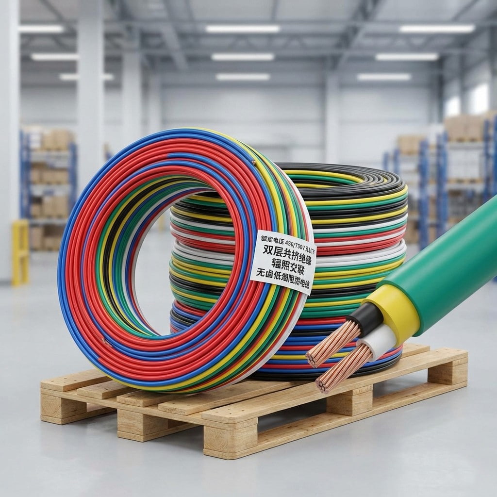
Product Overview: This product utilizes a double-layer co-extrusion insulation and electron irradiation cross-linking process, possessing halogen-free, low-smoke, and flame-retardant properties. It i...
See Details
How Do You Choose the Right Electrical Equipment Cable Without Causing System Failures?
Jun 17,2026
Content
- 1 What Are Electrical Equipment Cables?
- 2 Core Cable Types and Their Applications
- 3 Key Technical Ratings You Must Verify
- 4 International Standards Governing Cable Selection
- 5 Insulation and Jacket Materials Compared
- 6 Frequently Asked Questions
- 6.1 What is the difference between electrical equipment cables and building wire?
- 6.2 Can I use a PVC-insulated cable in a high-temperature motor application?
- 6.3 How do I calculate the correct conductor cross-section for my load?
- 6.4 Are shielded cables always necessary for control and instrumentation?
Selecting the correct electrical equipment cables is one of the most consequential decisions in any industrial or commercial installation. The wrong cable does not merely underperform — it creates fire hazards, accelerates insulation failure, and voids equipment warranties. This guide gives engineers, procurement managers, and facility teams the technical grounding to choose with confidence.
38% of industrial electrical failures are attributed to incorrect cable selection or substandard insulation materials, according to IEC field studies.
What Are Electrical Equipment Cables?
Electrical equipment cables are purpose-engineered conductors designed to transmit power or signals within machinery, control panels, motors, and industrial systems. Unlike general building wire, these cables must tolerate mechanical stress, thermal cycling, chemical exposure, and continuous flexing — often simultaneously. A proper definition: electrical equipment cables are multi-functional conductors built to IEC, UL, or CSA standards, rated by voltage class, temperature range, and environmental resistance for use inside or between equipment enclosures.
"An electrical equipment cable is not just a conductor — it is a rated system: conductor alloy, insulation chemistry, shielding geometry, and jacket compound working together to meet a specific installation environment."
Core Cable Types and Their Applications
The category of electrical equipment cables spans several distinct families, each engineered for a different performance envelope.
Power Cables
Carry high-current supply to motors, drives, and transformers. Typically multi-core with XLPE or EPR insulation. Rated from 300V to 35kV depending on application tier.
Control Cables
Carry low-voltage signals between PLCs, sensors, and actuators. Require excellent shielding to prevent EMI-induced signal corruption in automated systems.
Instrumentation Cables
Transmit analog and digital process signals. Pairs are individually shielded and twisted to minimize cross-talk and maintain signal fidelity over long runs.
Flexible Cables
Withstand continuous bending cycles in robotics, drag chains, and cranes. Conductor stranding is ultra-fine; jackets use high-elasticity PUR or TPE compounds.
Key Technical Ratings You Must Verify
Every specification sheet for electrical equipment cables contains several ratings that directly govern safe operation. Misreading even one parameter can result in thermal runaway or regulatory non-compliance.
| Rating Parameter | Typical Range | Why It Matters |
| Voltage Class | 300V / 600V / 1kV / 35kV | Determines insulation wall thickness and clearance requirements |
| Temperature Rating | 60C / 75C / 90C / 105C | Sets allowable ampacity and ambient operating limit |
| Conductor Cross-Section | 0.5mm to 630mm | Governs current-carrying capacity and voltage drop |
| Bending Radius | 4x to 12x OD | Prevents insulation cracking in routed installations |
| Short-Circuit Rating | 1kA to 50kA | Ensures cable survives fault events without catastrophic failure |
International Standards Governing Cable Selection
Compliance with recognized standards is not optional for electrical equipment cables used in regulated industries. The three dominant frameworks are IEC 60227 and IEC 60245 for insulated cables globally, UL 44 and UL 83 for North American markets, and BS EN 50525 for the European harmonized series. Cables destined for hazardous locations must also meet IECEx or ATEX certification requirements, which add gas group and temperature class markings.
Identify the installation environment: indoor dry, outdoor UV-exposed, underground, submerged, or hazardous area. Each demands a different jacket and insulation chemistry.
Calculate the continuous current load and apply derating factors for ambient temperature, conduit fill, and grouping according to IEC 60364-5-52 tables.
Determine the required mechanical protection level: cables in cable trays need oil resistance; cables in drag chains need torsion and flex endurance ratings.
Confirm the applicable standard for your market and verify the cable carries the corresponding certification mark — not merely a claim of compliance.
Insulation and Jacket Materials Compared
The polymer chemistry of insulation and jacket compounds determines how electrical equipment cables perform under heat, chemicals, and mechanical abuse. PVC remains the most widely used insulation material due to low cost and broad chemical resistance, but it softens above 70C and emits toxic gases during combustion. XLPE (cross-linked polyethylene) withstands continuous 90C operation and superior moisture resistance, making it the preferred choice for motor feeders and outdoor power distribution. For robotic and high-flex applications, PUR (polyurethane) jackets deliver tensile strength, hydrolysis resistance, and a flex-cycle life exceeding 10 million bends.
70C PVC Max Continuous Temp
90C XLPE Max Continuous Temp
10M+ PUR Flex Cycle Rating
Frequently Asked Questions
What is the difference between electrical equipment cables and building wire?
Building wire is designed for static installation inside conduit or walls with no mechanical stress. Electrical equipment cables are engineered for dynamic environments inside machinery — with higher flex ratings, oil-resistant jackets, tighter conductor stranding, and often EMI shielding that building wire does not require.
Can I use a PVC-insulated cable in a high-temperature motor application?
Standard PVC insulation is rated to 70C continuous — insufficient for most motor terminal connections where ambient temperatures routinely exceed that level. Specify XLPE or EPR insulation rated to 90C or 105C for motor feeder and connection cables.
How do I calculate the correct conductor cross-section for my load?
Start with the full-load current of the equipment, apply a derating factor from IEC 60364-5-52 based on installation method and grouping, then select the next standard conductor size above the derated value. Always verify voltage drop does not exceed 3% for power circuits or 1% for sensitive instrumentation circuits.
Are shielded cables always necessary for control and instrumentation?
Shielding is mandatory when cables run parallel to power conductors or in environments with high-frequency drive noise (VFDs). For short runs in clean electrical rooms with dedicated signal trays, unshielded twisted pairs may be acceptable — but foil or braid shielding grounded at one end is best practice for any analog signal cable exceeding 3 meters.
Related products
-
-
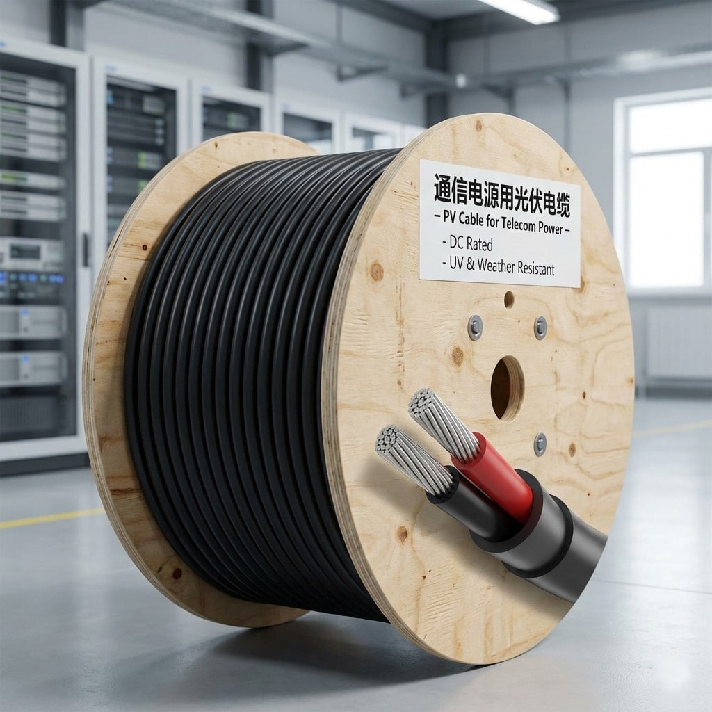
Product Overview: Designed specifically for photovoltaic power supply systems in communication base stations, data centers, etc., this product transmits DC power from photovoltaic modules to communica...
See Details -
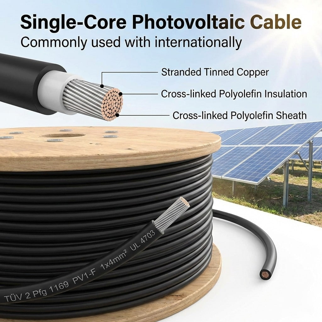
Product Overview: This series of photovoltaic cables is a dedicated cable designed specifically for solar photovoltaic power generation systems, used to connect photovoltaic modules, combiner boxes, a...
See Details -
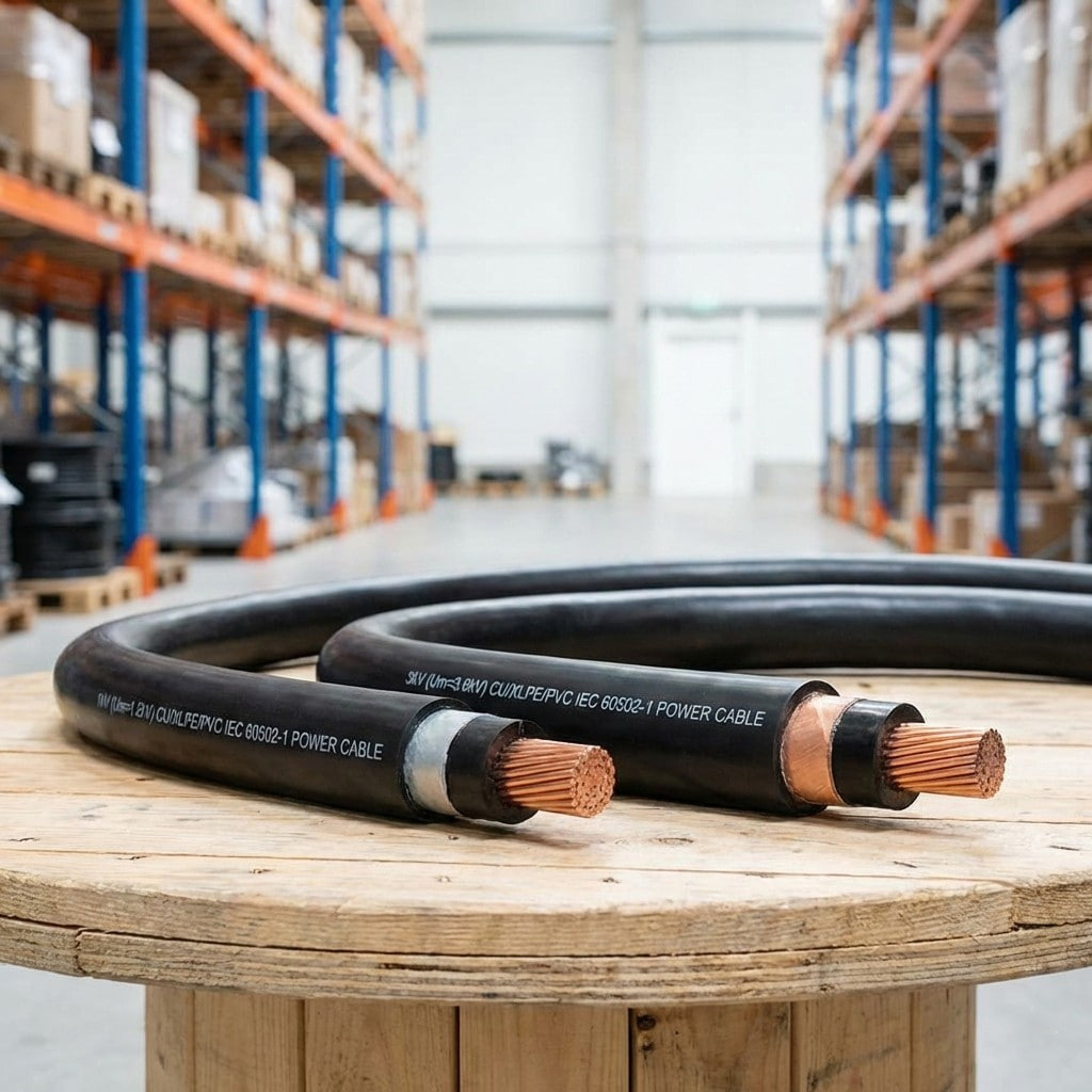
Product Definition: Low-voltage extrusion-insulated power cable for 1kV and 3kV systems, made with high-conductivity copper or aluminum conductors and premium extrusion insulation.
See Details -
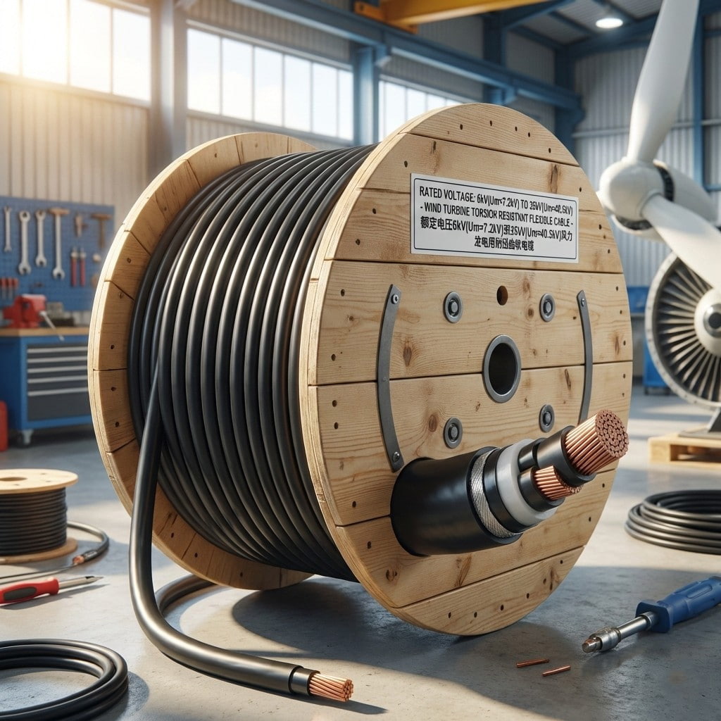
Product Overview: This series of products consists of high-performance, torsion-resistant flexible cables specifically designed for the harsh environments of wind turbine generators. Rated voltages ra...
See Details -
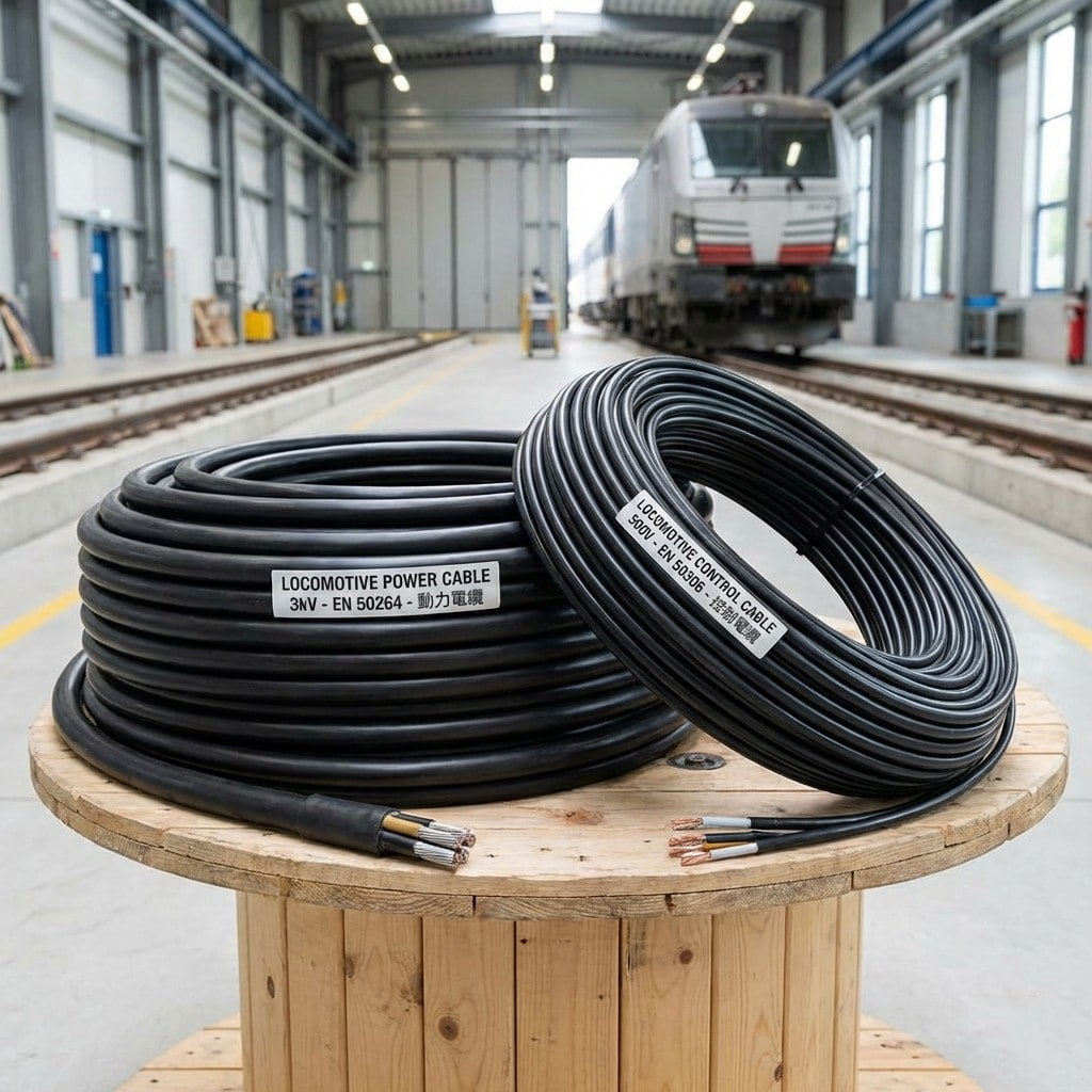
Product Introduction: Locomotive and rolling stock cables are specifically designed for the rail transit industry, covering both power supply and control signaling. The cables utilize highly flexible ...
See Details
- About Us
- Company Profile
- History
- Smart Factory
- Resources
- Resources
- Technical Datasheets
- Product Catalogs
- Certificates & Compliance
- Industry Standards
- FAQs
- News
- Products
- Power Cables
- Electrical Equipment Cables
- Wind Power Cables
- Photovoltaic / Energy Storage Cables
- Overhead Cables
- Rail Transit
- Contact
- Contact
- Contact Meaia
-
Mobile QR code

Back to top

