
 English
  中文简体
中文简体 

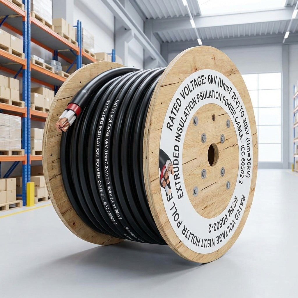
Product Definition: Medium-voltage extrusion-insulated power cable for 6kV to 30kV systems, using high-quality copper or aluminum conductors and premium insulation materials, designed for medium-volta...
See Details
Custom Equipment Cables Manufacturer: What to Specify Before You Order
Sep 03,2026
Content
- 1 What a custom equipment cables manufacturer needs to know first
- 2 Custom equipment cables: six specifications to lock down before sending a drawing
- 3 How a manufacturer engineers the cable around your equipment
- 4 Standards and certifications decide which cable goes where
- 5 How to verify a custom equipment cables manufacturer's production floor
- 6 Frequently asked questions about custom equipment cables
At a food packaging plant, a batch of 24V proximity switch cables failed within six months because the jacket was PVC, not PUR. Machine oil seeped through the molecular structure, swelled the insulation, and shorted the conductors. The replacement cable was a custom build with a PUR jacket. A custom equipment cables manufacturer does not just extrude cable to your drawing; it translates your operating conditions into a physical construction that survives them. That translation is the entire value of going custom.
What a custom equipment cables manufacturer needs to know first
The most important input is the operating environment. Temperature range, flexing frequency, chemical exposure, and voltage stress determine conductor stranding, insulation compound, and jacket material. Without those four inputs, a manufacturer cannot make an informed recommendation.
The temperature range is the first constraint because it sets the insulation compound. A cable that loses adhesion at 70 deg C will fail in a control cabinet next to a servo drive. Flexing frequency is the second constraint because it determines conductor stranding; the finer the strands, the longer the cable survives repeated bending. Chemical exposure decides the jacket. Voltage defines the insulation thickness and the clearance between cores.
-40 deg C to +105 deg C Operating range for a PVC and XLPE custom cable
450/750V Standard equipment cable voltage rating
Class 5 Fine-wire stranding for continuous flex
6x OD Minimum bend radius at 20 deg C for a flexible control cable
Custom equipment cables: six specifications to lock down before sending a drawing
The drawing is the contract. The more explicitly you define these six areas, the less room a manufacturer has to substitute a material that seems equivalent but is not. Most substitution disputes happen because a specification says only equivalent to without defining what equivalent means for temperature, shielding coverage, or jacket hardness.
| Specification | What it controls | Typical custom choice | Why it matters |
| Conductor | Current capacity, voltage drop, flexibility | Tinned copper, Class 5 stranding | Tinned surface resists oxidation; fine stranding reduces flex fatigue |
| Insulation | Maximum conductor temperature | XLPE, PVC, halogen-free | XLPE runs 90 deg C continuous; PVC is limited to 70 deg C |
| Voltage rating | System insulation coordination | 450/750V, 1kV, 1.8kV | A mismatch causes premature breakdown during surges |
| Shielding | Signal integrity under EMI | Braided 85% coverage, foil, foil-plus-braid | Braid blocks low-frequency noise; foil blocks high-frequency RF |
| Jacket | Mechanical protection, chemical resistance | PUR, PVC, LSZH | PUR resists oil; LSZH reduces smoke in confined spaces |
| Temperature range | Continuous and emergency limits | -40 deg C to 105 deg C | Defines the long-term operating envelope |
How a manufacturer engineers the cable around your equipment
Every custom equipment cable is a compromise among electrical, mechanical, and thermal requirements. An experienced manufacturer balances them deliberately.
Conductors
The conductor is the starting point. For equipment cables, the most common construction is tinned copper with Class 5 stranding; the many fine wires let the cable bend without work-hardening. If the cable will be subject to continuous flexing, stranding must be designed for repeated motion, not just for installation.
Insulation and jacket
Insulation materials are the main temperature limiter. PVC handles 70 deg C continuous; XLPE handles 90 deg C. For high-temperature equipment near motors or process heat, a silicone or halogen-free XLPE compound extends the limit past 150 deg C. The jacket is a separate decision: PUR for oil and abrasion, PVC for cost, halogen-free low-smoke (LSZH) for enclosed spaces where fire toxicity matters.
Insulation rating comparison for common compound families
PVC
70 deg C
XLPE
90 deg C
Halogen-free XLPE
90 deg C
Silicone
180 deg C
Shielding
In a control cabinet, signal and power cables often share a cable tray. A tinned copper braid with 85% coverage blocks most low-frequency interference. A foil shield gives continuous coverage against high-frequency noise. A combined braid-and-foil construction handles both but costs more and is harder to terminate. For high-reliability equipment, the shielded cable is designed for the specific EMI spectrum of the machine.
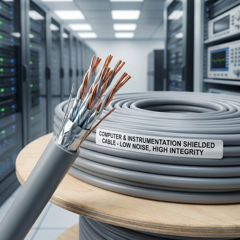 Computer and Instrument Shielded CableComputer and Instrumentation Shielded Cable is a high-performance shielded cable designed specifically for industrial automation control, instrument signal transmissio...View Product →
Mechanical flex and torsion
Cable carriers and robot arms subject cable to repeated bending and twisting. The critical area is the transition where the cable enters the moving device; strain relief must be engineered into the cable, not added as a connector accessory. Torsion-balanced cores, where the layers are designed so that twisting does not unwind them, separate a cable that lasts 10,000 flex cycles from one that survives 1,000,000.
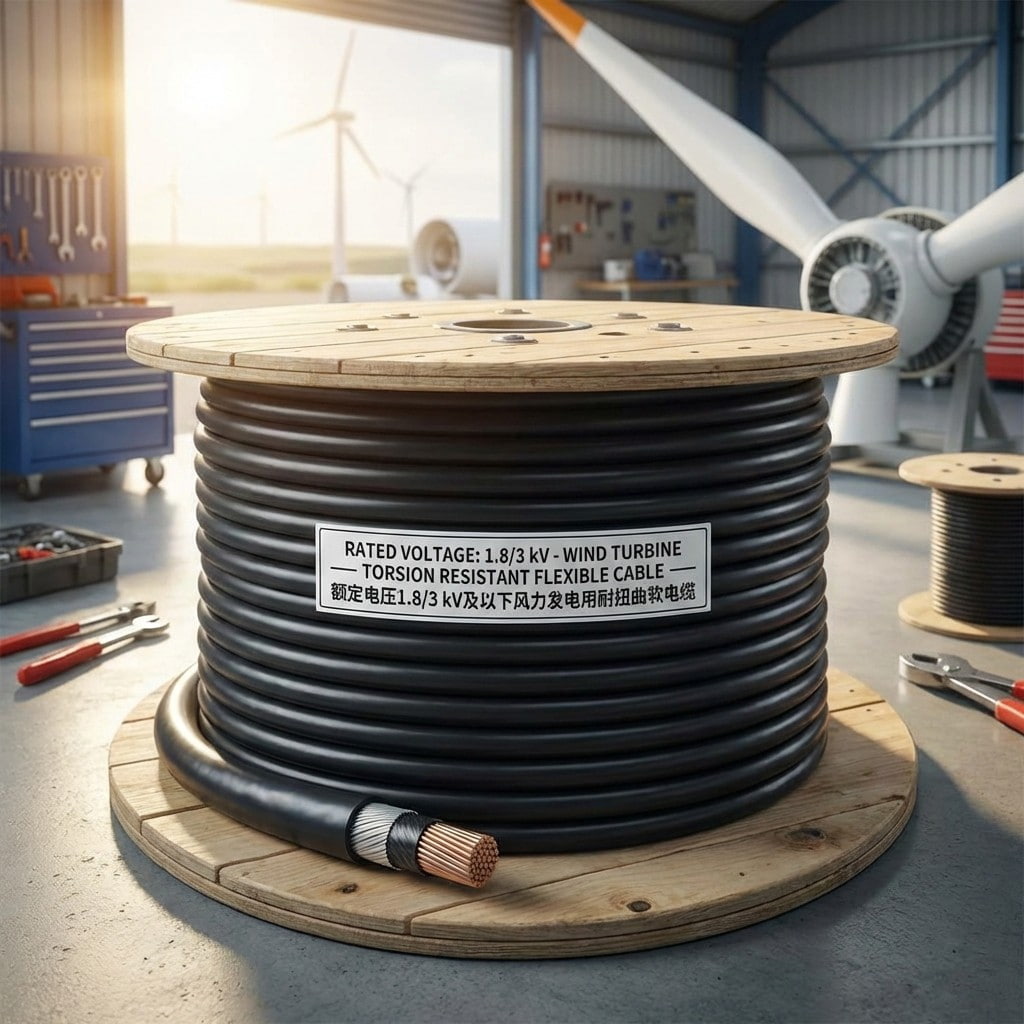 Torsion-resistant Flexible Cable for Wind Power, Rated Voltage 1.8/3kV and BelowProduct Introduction:View Product →
Standards and certifications decide which cable goes where
Standards are the minimum technical baseline for an application. When a standard applies, it is not something to negotiate away. The standard controls test methods, tolerances, and marking, and it gives the end user a way to verify that the cable is what the drawing says it should be. In custom equipment cable, the relevant standards are not all equally demanding.
| Standard | Applies to | Key requirement |
| IEC 60227 | PVC insulated equipment cables | 450/750V rating, H05 and H07 series |
| IEC 60502 | Extruded power cables | 1kV to 35kV, XLPE insulation |
| GB/T 9330 | Control cables | Construction and test methods for control cables |
| IEC 62852 | Photovoltaic cables | 1.5kV DC, UV-resistant, XLPO insulation |
| EN 45545 | Rail transit cables | Fire, smoke, and toxicity performance |
For a photovoltaic system, the cable must carry 1.5kV DC and endure decades of UV exposure. IEC 62852-compliant construction is mandatory. The same logic applies to wind power: the torsion-resistant cable in the nacelle must comply with specific mechanical endurance specifications.
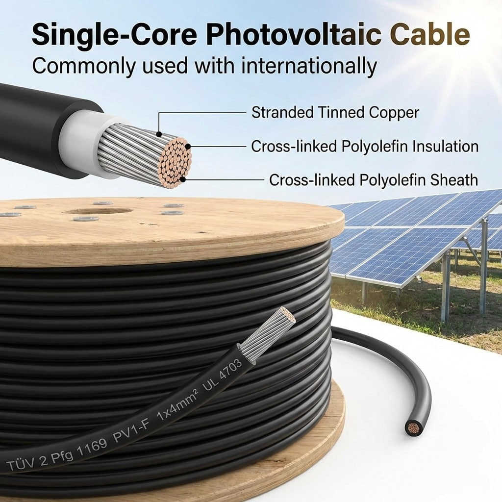 PV System CableThis series of photovoltaic cables is a dedicated cable designed specifically for solar photovoltaic power generation systems, used to connect photovoltaic modules, co...View Product →
How to verify a custom equipment cables manufacturer's production floor
The factory is the proof. The capability you can see, including floor area, testing lab, and traceability system, determines what engineering risk the supplier can absorb. A small workshop that buys compound and extrudes on a single line can handle a one-off batch, but it cannot consistently deliver 100,000 meters of a cable that passes every test on every drum.
- 1
Production floor size. A 40,000 m2 factory can dedicate separate extrusion lines to different batches without cross-contamination.
- 2
Full-process MES. Digital traceability from conductor drawing to final test gives you a complete production record.
- 3
In-house testing lab. The supplier should test conductor resistance, insulation resistance, and dielectric strength, not just perform a visual check.
- 4
Environmental documentation. ISO 14001 certification and published product carbon footprint reports show a supplier managing more than bulk cable cost.
Ask for the production flow map. A manufacturer that shows you how the cable is made, and how it is tested, is the one that can make it right the first time.
Before you order, talk to the engineering team about your operating conditions. The conversation takes an afternoon and gives you a clear specification document, a material recommendation, and a timeline. That is a much better outcome than discovering a problem after the cable is on the machine.
Frequently asked questions about custom equipment cables
What is the minimum order quantity for a custom equipment cable?
For equipment cables with 0.5mm2 to 4mm2 conductors, typical minimum orders run from 500m to 1,000m. Larger conductor sizes or custom jacket compounds may require longer minimum lengths because of extrusion line setup costs. A manufacturer with multiple extrusion lines can often accept shorter runs than one operating a single line.
Can a manufacturer match an existing cable sample?
Yes. A competent custom equipment cables manufacturer can reverse-engineer a sample by measuring conductor stranding, insulation thickness, and sheath compound. Request a material analysis report before replacing a legacy part number; it protects you from a supplier that simply scrapes off the marking and substitutes a cheaper compound.
Do I need shielding on an equipment cable?
If the cable runs parallel to a power line for more than a meter, or if it carries low-level analog signals, shielding is recommended. A braided tinned copper shield with 85% coverage is the most common choice for industrial equipment cables. For variable-frequency drives, a foil-braid combination is more effective at blocking high-frequency harmonic noise.
How long does a custom cable order take?
A typical custom equipment cable run takes 3 to 6 weeks from spec confirmation to delivery, depending on compound and conductor availability. Prototype samples are usually available within 10 days of engineering review. If the cable is a modification of an existing design, the lead time is usually shorter.
Related products
-
-
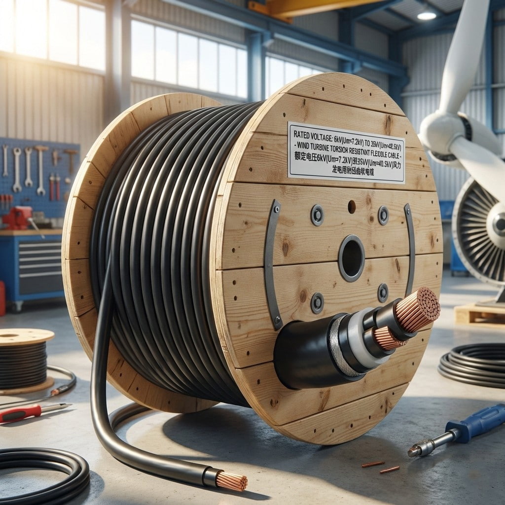
Product Overview: This series of products consists of high-performance, torsion-resistant flexible cables specifically designed for the harsh environments of wind turbine generators. Rated voltages ra...
See Details -
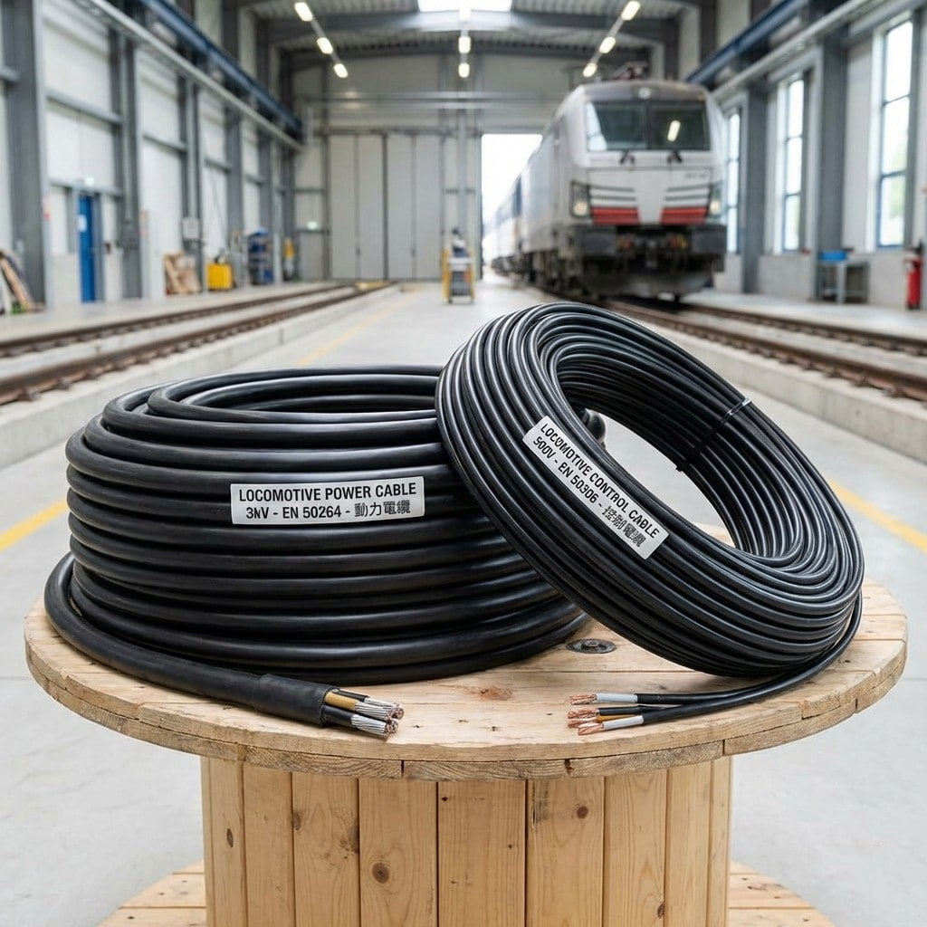
Product Introduction: Locomotive and rolling stock cables are specifically designed for the rail transit industry, covering both power supply and control signaling. The cables utilize highly flexible ...
See Details -
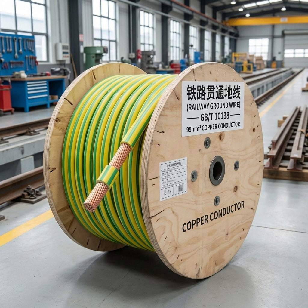
Product Overview: Railway through grounding wires are dedicated grounding conductors laid along the entire length of a railway line, forming the core framework of the railway's integrated grounding sy...
See Details -
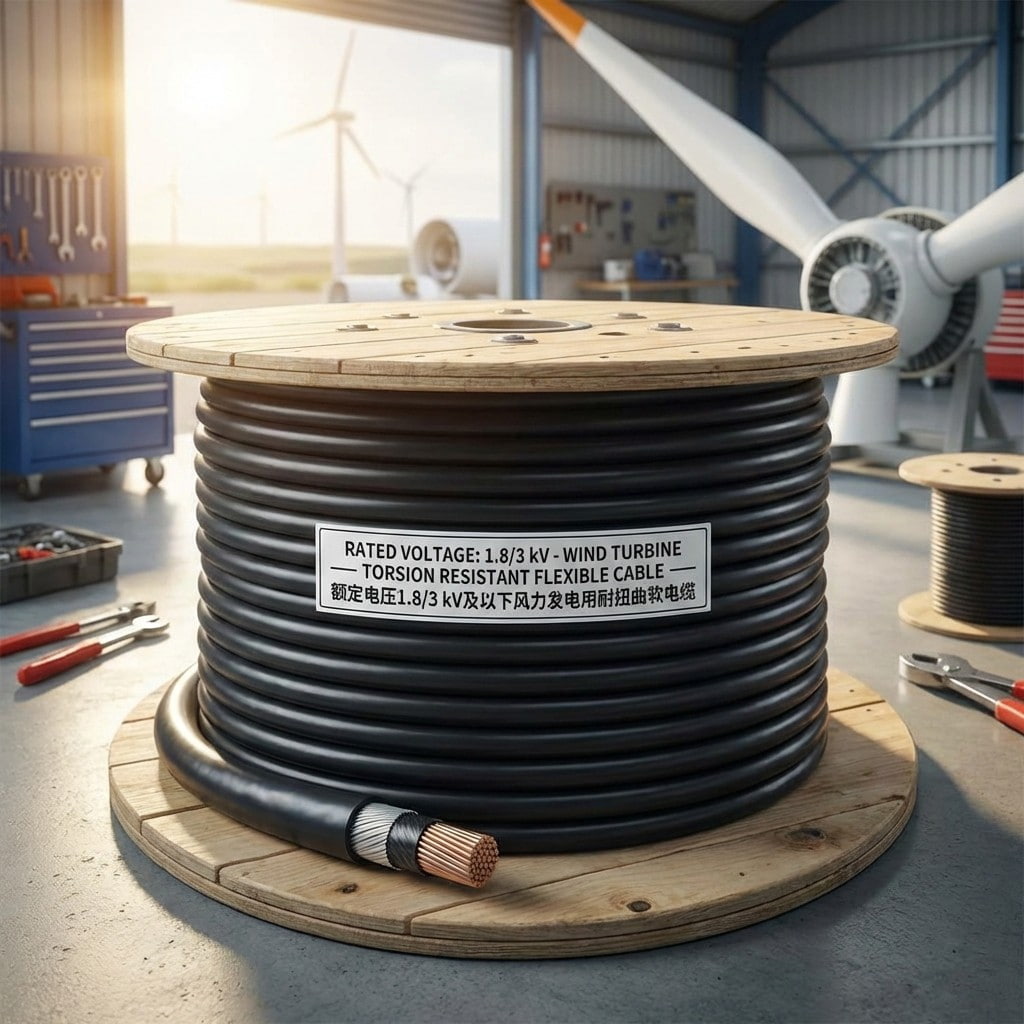
Product Introduction: Designed specifically for the harsh operating environment of wind power systems, meeting the requirements of continuous torsion and bending during mobile installation within the...
See Details -
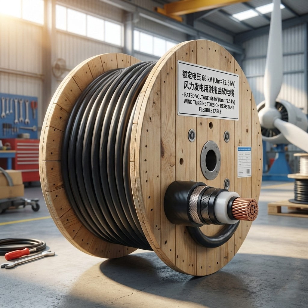
Product Introduction: This cable is specifically designed for medium- and high-voltage wind power generation equipment, with a rated voltage of 66 kV. It is suitable for high-reliability power transmi...
See Details
- About Us
- Company Profile
- History
- Smart Factory
- Resources
- Resources
- Technical Datasheets
- Product Catalogs
- Certificates & Compliance
- Industry Standards
- FAQs
- News
- Products
- Power Cables
- Electrical Equipment Cables
- Wind Power Cables
- Photovoltaic / Energy Storage Cables
- Overhead Cables
- Rail Transit
- Contact
- Contact
- Contact Meaia
-
Mobile QR code

Back to top

